Torque limiting clutch adjustment, Drive motor brake adjustment/removal, See figure 2-4. & figure 2-5.) – JLG 20VP (3120728) Service Manual User Manual
Page 24: Torque limit clutch - adjustment components -6, Brake assembly components -6
SECTION 2 - SERVICE PROCEDURES
2-6
– JLG Lift –
3120728
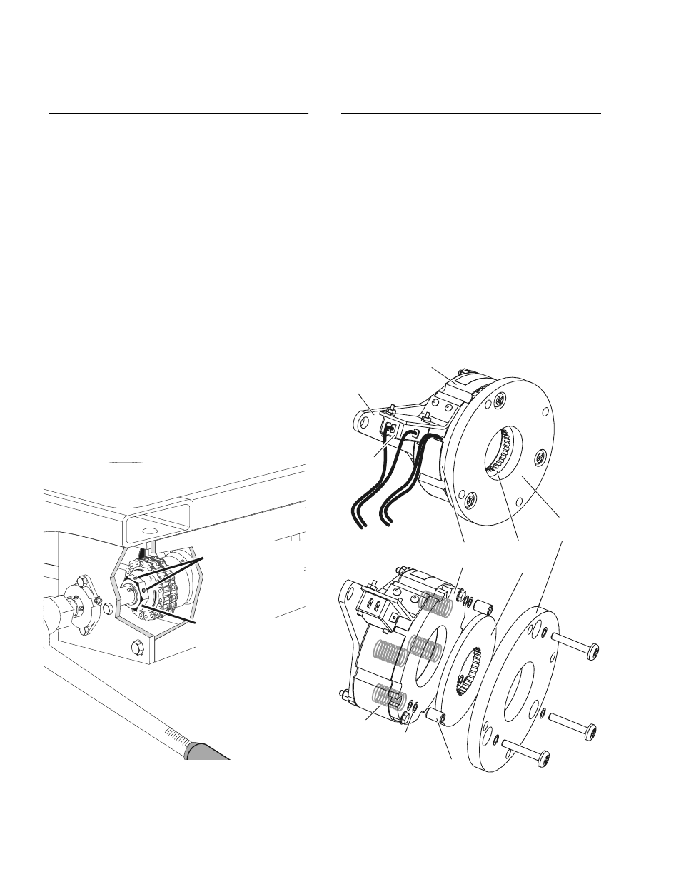
Torque Limiting Clutch Adjustment
NOTE: The large adjusting nut on the side of the clutch
assembly is a standard type thread.
If the torque (slip) setting of the clutch assembly is
under spec (by more than 35 ft. lb.), the large adjust-
ing nut must be (tightened) turned clockwise to
increase the torque setting.
If the torque (slip) setting is over spec (over 185 ft.
lb.) the large adjusting nut must be (loosened),
turned counter-clockwise to decrease the torque set-
ting.
1.
Loosen the two (2) adjusting nut setscrews located
on the large adjusting nut on the clutch assembly.
(See Figure 2-3.)
2.
Hold the drive axle steady using service tool (P/N-
0080229) and the torque wrench used to check the
torque setting.
3.
Depending on how far off the original torque setting
was (see note at beginning of this procedure),
tighten or loosen the adjusting nut accordingly, then
recheck the (slip) torque setting.
4.
When proper torque setting is achieved, re-tighten
the two (2) adjusting nut, setscrews.
5.
Re-install the drive wheels, remove the jack stand
and lower the machine to ground.
Drive Motor Brake Adjustment/Removal
(See Figure 2-4. & Figure 2-5.)
Mounted onto the front of each drive motor housing is a
brake assembly. The brakes are normally ENGAGED
(brakes on) when the machine is parked and are
RELEASED electrically (brakes off) under normal driving
conditions, when the joystick is enabled and pushed in
any direction. The brakes can also be RELEASED manu-
ally using the manual brake release lever mounted on the
side of the mast.
NOTE: The brakes are intended only as parking brakes to
keep the machine from moving while at rest. The
brakes are not used to stop the machine during driv-
ing operations, this braking is controlled by the drive
motors themselves. Under normal driving conditions,
once released the brakes are not engaged again
until the machine comes to a complete stop.
Figure 2-3. Torque Limit Clutch -
Adjustment Components.
TORQUE LIMIT
CLUTCH
ADJUSTING NUT
ADJUSTING NUT
SET SCREWS
Figure 2-4. Brake Assembly Components
FRICTION
BRAKE
DISK
ARMATURE
PLATE
SPACER
SPRINGS
SHIM WASHERS
(AS REQUIRED)
MOUNTING
PLATE
MANUAL
BRAKE
RELEASE
ARM
MAGNETIC
COIL
HOUSING
LIMIT
(MICRO)
SWITCH