Hub shaft sub-assembly procedure, Hub shaft sub-assembly procedure -58 – JLG 460SJ Service Manual User Manual
Page 110
SECTION 3 - CHASSIS & TURNTABLE
3-58
– JLG Lift –
3120895
25. The Cover (6) is now installed on this assembly. Tak-
ing care to correctly align Pipe Plug hole (20) with
those in the Hub (1J), usually 90
o
to one another.
Locate the 4 counterbore holes in Hub (1G) [marked
in Step 3] and install 4 Shoulder Bolts (13). A slight
tap with a hammer may be necessary to align Shoul-
der Bolt with Hub (1G) counterbore.
26. Install regular Grade 8 Bolts (12) into remaining
holes.
27. Pipe Plugs(20) are to be installed into Cover (6)
using a lubricant seal of some sort.
28. Torque Shoulder Bolts (13) to 23-27 ft.lbs. (31-37
Nm) and regular Grade 8 Bolts (12) to 23-23 ft.lbs.
(31-37 Nm)
This completes the assembly. The unit must be filled com-
pletely with EP 90 lubricant when mounted vertically
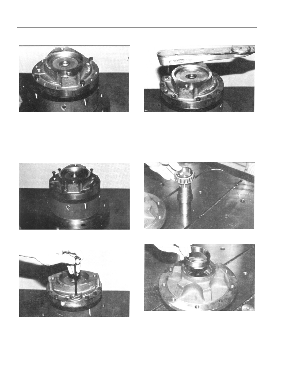
Hub Shaft Sub-Assembly Procedure
1. Press Bearing Cone (1D) onto Shaft (1A).
2. Press Bearing Cup (1C) into Hub (1G) taking care to
insure cup start square with the bore of Hub (1G).