Verdrahtungsplan/ wiring diagram – IKA C-MAG HP 10 User Manual
Page 35
35
CMAG 012014
A-A
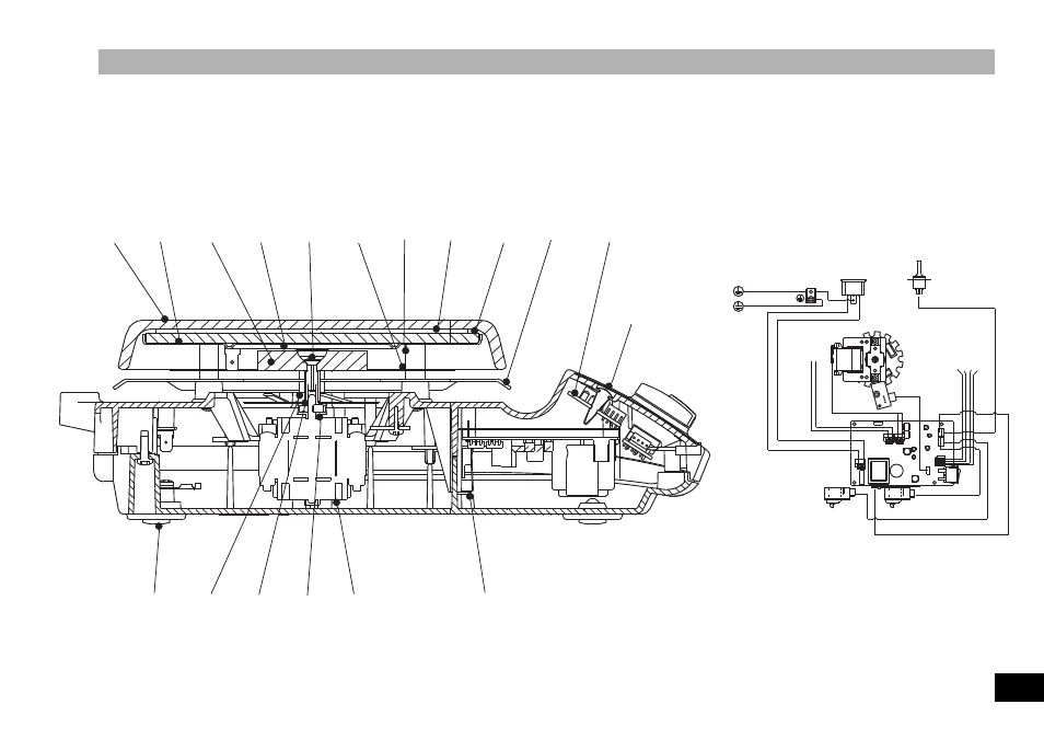
Verdrahtungsplan/ Wiring diagram
Litzenkennzeichnung nach IEC 757
Strandet conductor color coding to IEC 757
Display
Potentiometer
Heater
Potentiometer
Motor
GN YE RD BU
GN YE RD BU
31
76
41
58
7
40
32
33
65
35
70
71
59
18
17
38
2002
--
+
+
GN YE RD BU
BLP
GN YE RD BU
Temperaturaufnehmer
Temperature sensor
Motor
Folienheizung
Heating foil
BN
B
K
B
N
W
H
W
H
+
+
GN YE RD BU
Kontaktstecker
Contact plug
Gerätestecker
Connector plug
Gehäuse-Oberteil
Upper housing
Gehäuse-Unterteil
Lower housing
Aufstellplatte
Heating surface
GN YE
GN YE
GN YE
54
--
Spare parts diagram/ Ersatzteilbild/ Tableau des pièces de rechange/Peças de reposição esquema
This manual is related to the following products: