Main components of the hand pump 4, Functional description 5 – Lukas LH 2/ 1,8-70 DIN User Manual
Page 8
8
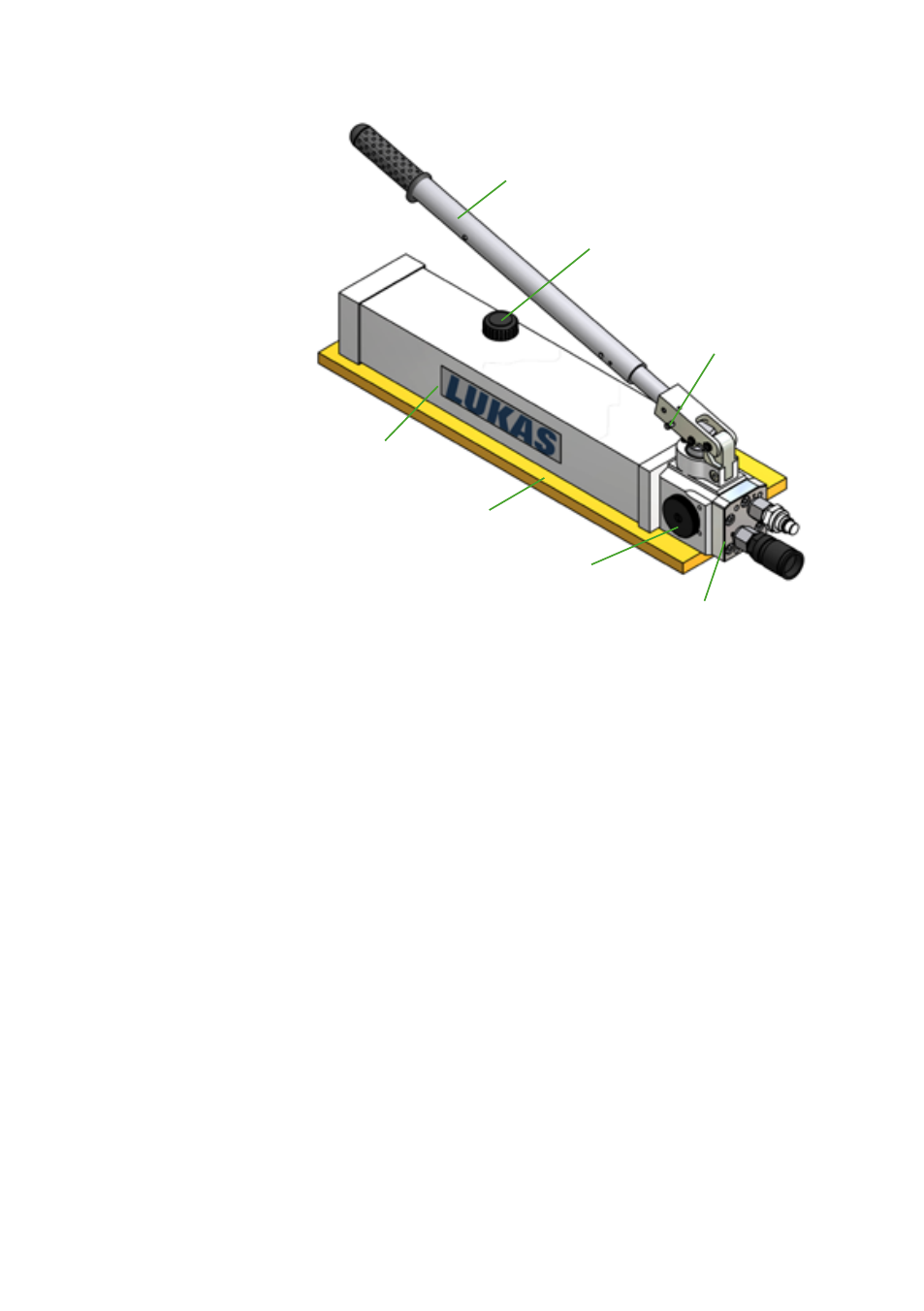
Main components of the hand pump
4.
1
2
3
4
5
6
7
1 Drain valve
2 Connection plate with
fittings or couplings
3 Vent / fill cap
4 Retractable pump
lever
5 Tank
6 Lock
7 Base plate
Functional description
5.
5.1 Base pump
All LUKAS hand pumps of this series are two-speed, i.e. they have two operating speeds:
• A high speed in the low pressure range (LP) for fast extension of the cylinder or device
while unloaded
• A low speed in the high pressure range (HP) for controlled extension of the cylinder or
device while loaded
The switch from low pressure (LP) to high pressure (HP) is automatic at the factory setting
for changeover pressure (see chapter "Technical Data").
A pressure port "P" with a G1/4" thread and a return port "T" with an M10 thread are directly
available as ports on the pump.
To connect rescue equipment, adapter blocks must be installed (see subchapter "Adapter
blocks" for more information). In the case of the hand pumps sold by LUKAS, one of these
adapter blocks is always included as standard equipment and is already installed.
Of course, the installed adapter blocks may be replaced with other ones. However, you must
contact an authorised LUKAS dealer or contact LUKAS directly.
The retractable handle of the LUKAS hand pump combines low required pumping force with
compact dimensions for storage and transport.
In addition, the LUKAS hand pumps for rescue equipment are equipped with a base plate to
ensure a more stable position during operation.