The economical heating choice, Ease of service, Designed for safety – Burnham Minuteman II User Manual
Page 3: Dimensions (all sizes) & standard equipment, Burnham's minuteman
3
The Economical
Heating Choice
Burnham's Minuteman
®
II
boiler is efficient by design. At
the heart of every Minuteman II
is a dependable cast iron heat
exchanger that not only
enhances energy efficiency, but
also improves boiler perfor-
mance. A draft inducing fan
pulls hot gases through the heat
exchanger at just the right speed
for optimum efficiency. Together,
the heat exchanger and fan
provide for more heat with less
fuel and eliminate heat loss
through the vent. No vent damper
is required.
Ease of Service
The Minuteman II unit is
equipped with split controls: an
operating/high limit control, a
transformer, and a circulator relay.
By using "off-the-shelf" separate
controls instead of a combination
control, Burnham has simplified
control replacement and reduced
replacement costs.
The location of the controls
also makes regular servicing
easier because everything is up
front.
Designed for Safety
The Minuteman II boiler/water
heater's sleek blue jacket gives a
clean appliance look to the
installation, plus it's designed with
safety in mind.
All controls are safely hidden
behind the two front panels. The
top panel is only removable by an
adult-sized person. For added
safety, the middle and bottom
panels on the Minuteman II
combination unit are secured with
screws and cannot be removed
without tools.
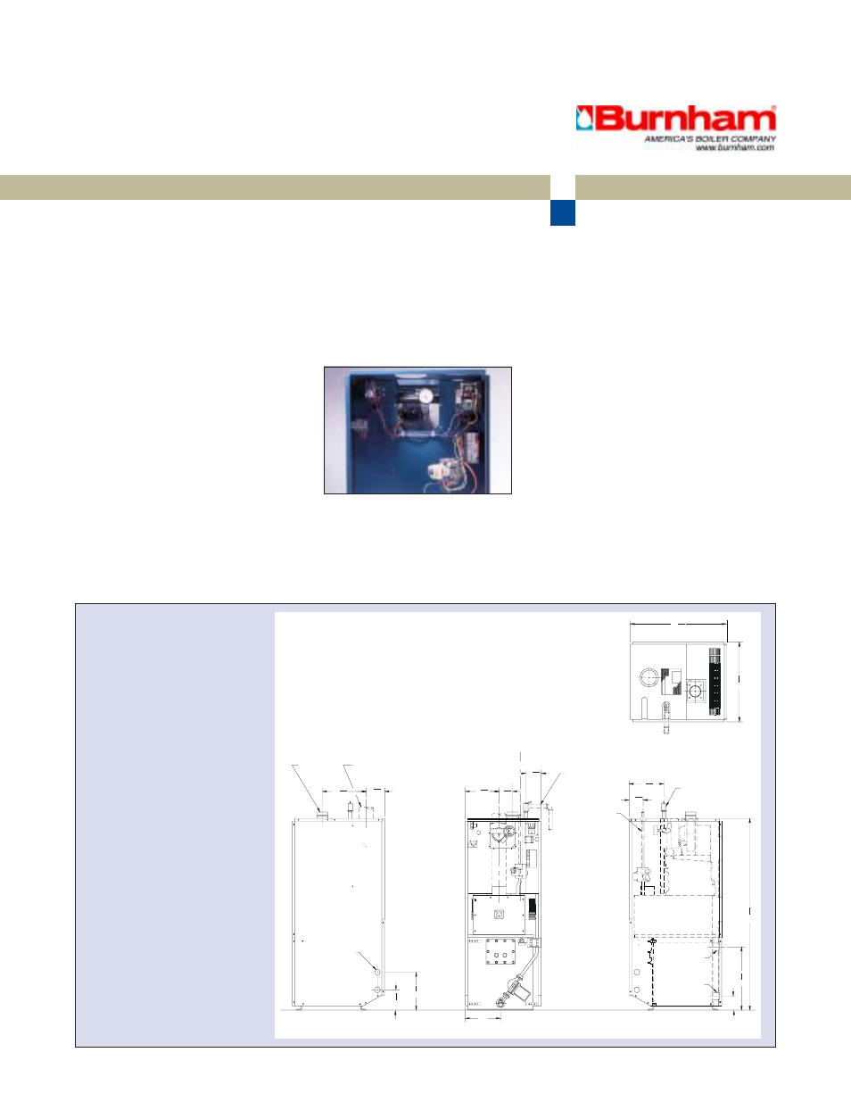
Dimensions (All Sizes)
& Standard Equipment
STANDARD EQUIPMENT
Section assembly
Deluxe insulated jacket
Tank circulator
High limit
Electronic ignition
100% shut-off combination
Step-opening gas valve
Safety relief valve 30 PSI
Induced draft fan
Differential suction pressure
switch
Vent monitor
Boiler water monitor switch
Transformer/relay
Boiler drain valve
Pressure-temperature gauge
Tank aquastat
AL29-4C vent connector
AL29-4C terminal
Combustion air intake terminal
3 DIA
VENT
4 DIA AIR
INTAKE
12
7
16
16
5
3
ALTERNATE
DOMESTIC
WATER PIPING
ACCESS (K.O.)
(TYP)
5
3
4
(TYP)
3
(TYP)
10
LEFT SIDE VIEW
GAS PIPING
16
RELIEFVALVE PIPING
C
L
C
L
C
L
VENT
PIPING IN HIDDEN
OUTLINE NOT
FURNISHED
BY MANUFACTURER
AIR
INTAKE
9
13
16
3
3
8
4
FRONT VIEW L/DOOR
10
GAS PIPING
15
16
3
13
9
RELIEF VALVE
HOUSE HEATING
SUPPLY
CONNECTION
54
HOUSE HEATING
RETURN
CONNECTION
15
16
17
4
TOP VIEW
9
16
21
1
8
26
RIGHT SIDE VIEW
4
9
16
5
16