Bryant R-22 561G User Manual
Page 4
Use furnace transformer, fan-coil transformer, or accessory trans-
former for control power, 24v/40va minimum.
NOTE: Use of available 24v accessories may exceed the mini-
mum 40va power requirement. Determine total transformer load-
ing and increase the transformer capacity or split the load with an
accessory transformer as required.
IX.
COMPRESSOR CRANKCASE HEATER
1. When equipped with a crankcase heater, energize heater a
minimum of 24 hr before starting unit. To energize heater
only, set thermostat to OFF mode and close electrical
disconnect to outdoor unit.
A crankcase heater is required if refrigerant tubing is longer than
80 ft.
X.
INSTALL ELECTRICAL ACCESSORIES
Refer to individual instructions packaged with kits or accessories
when installing.
XI.
START-UP
CAUTION: PERSONAL INJURY HAZARD
Failure to follow this caution may result in personal
injury.
Service valve gage ports are equipped with Schrader
valves. Wear safety glasses and gloves when handling
refrigerant.
1. Fully open liquid and vapor service valves.
2. Unit is shipped with valve stem(s) front seated (closed) and
caps installed. Replace stem caps after system is opened to
refrigerant flow. Replace caps finger-tight and tighten an
additional 1/12 turn with wrench.
3. Close electrical disconnects to energize system.
4. Set room thermostat at desired temperature. Be sure set
point is below indoor ambient temperature.
5. Set room thermostat to COOL and fan control to ON or
AUTO mode. Operate unit for 15 minutes. Check system-
refrigerant charge. (See Check Charge.)
WARNING: PERSONAL INJURY AND ENVIRNO-
MENTAL HAZARD
Failure to follow this warning could result in personal
injury or death. Relieve pressure and recover all refrig-
erant before system repair or final unit disposal. Use all
service ports and open all flow control devices, including
solenoid valves.
CAUTION: UNIT DAMAGE HAZARD
Failure to follow this caution may result in unit compo-
nent damage.
•
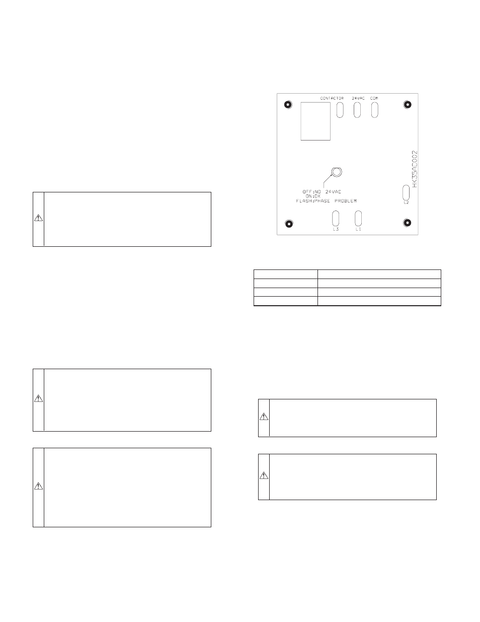
3-phase scroll compressors are rotation sensitive.
•
A flashing LED on phase monitor indicates reverse
rotation. (See Fig. 5 and Table 2.)
•
This will not allow contactor to be energized.
•
Disconnect power to unit and interchange 2 field
wiring leads on unit contactor.
A.
SEQUENCE OF OPERATION
Turn on power to indoor and outdoor units. Transformer is
energized.
On a call for cooling, thermostat makes circuits R-Y and R-G.
Three phase models with scroll compressors, are equipped with a
phase monitor to detect if the incoming power is correctly phased
for compressor operation. (See Fig. 5 and Table 2.) If the phasing
is correct, circuit R-Y energizes contactor, starting outdoor fan
motor and compressor circuit. R-G energizes indoor unit blower
relay, starting indoor blower motor on high speed.
NOTE: If the phasing is incorrect, the contactor will not be
energized. To correct the phasing, interchange any two of the three
power connections on the field side.
When thermostat is satisfied, its contacts open, de-energizing
contactor and blower relay. Compressor and motors stop.
If indoor unit is equipped with an off delay circuit, the indoor
blower can run an additional 120 sec to increase system efficiency.
XII.
CHECK CHARGE
UNIT CHARGE
Factory charge is shown on unit rating plate. Charge procedure is
shown on wiring/charging label locate on unit.
CAUTION: UNIT DAMAGE HAZARD
Failure to follow this caution may result in unit compo-
nent damage. Compressor damage may occur if system is
overcharged.
CAUTION: ENVIRNOMENTAL HAZARD
Failure to follow this caution may result in environmental
damage and fines. Federal regulations require that you do
not vent refrigerant to the atmosphere. Recover during
system repair or final unit disposal.
A.
Cooling Only Procedure—Indoor unit equipped with
piston, superheat method
Factory charge is shown on unit rating plate. To check charge in
cooling mode, refer to Cooling Only Procedure on unit wiring and
charging label.
NOTE: If superheat or subcooling charging conditions are not
favorable, charge must be weighed in accordance with unit rating
plate ± 0.6 oz/ft of 3/8-in. liquid line above or below 15 ft
respectively.
Fig. 5—3-Phase Monitor Control
A00010
TABLE 2—PHASE MONITOR LED INDICATORS
LED
STATUS
OFF
No call for compressor operation
FLASHING
Reversed phase
ON
Normal
—4—