J.P. Instruments EDM 730 Flight Manual Supplement User Manual
Page 3
J.P.INSTRUMENTS
Airplane/Rotorcraft Flight Manual
PO BOX 7033
Supplement No. 1
HUNTINGTON BEACH CA 92646
EGT-701
Rev B
Page 3 of 4
1-GENERAL
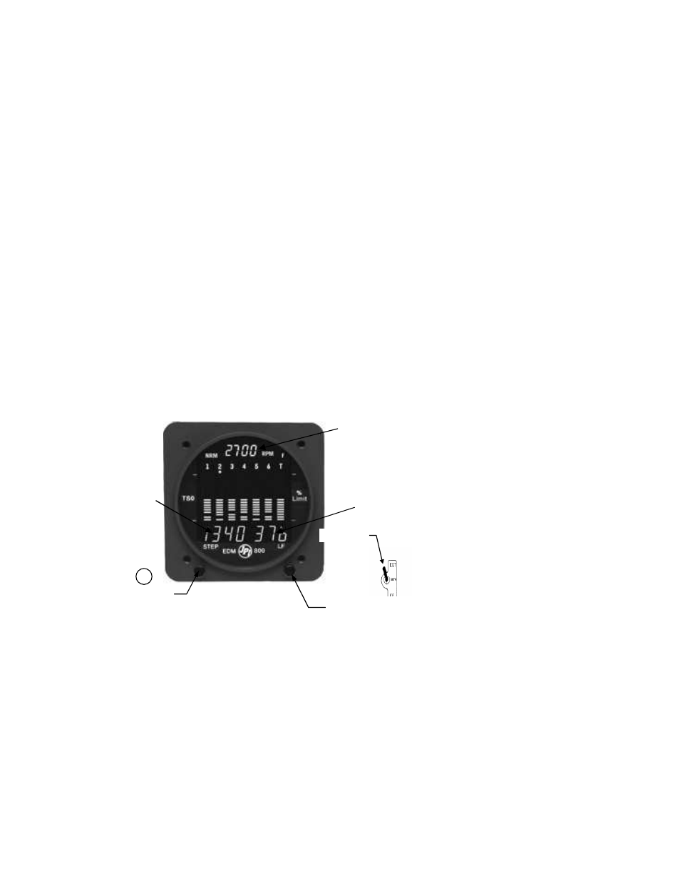
The EGT-701 temperature indicator displays temperature digitally and in analog format. The EGT as
displayed is based on probes located near the exhaust outlet for each cylinder and the TIT probe, if
installed, is adjacent to the turbo charger. These probes are not necessarily collocated with the
primary probes therefore, EGT-701 may not indicate the same as the aircraft primary instruments.
The analog display is an electronic bar graph (vertical columns, one per cylinder) of EGT & TIT
temperatures presented as a percentage of 1650
o
F. Below the vertical columns the specific value for
EGT and CHT are displayed digitally. The dot over the column indicates which cylinder's digital
information is presently displayed. The missing bars at the base of the columns indicates the hottest
and coldest Cylinder Head temperature trend . During Lean Find mode the leanest cylinder is
displayed along with the fuel flow (optional) at that time. Depressing the LF and STEP button
simultaneously brings up the adjustable scan rate function, OAT in
o
C or
o
F. Depress the LF button
will change the value of the rate or OAT in
o
C or
o
F. Exit by Depressing STEP.
If the EGT-701 buttons are not depressed for 10 minutes the system will start scanning
automatically. Depressing the STEP button will stop the automatic scan and index through all the
functions available. During constant power cruise, if the the LF button is depressed for five seconds
the bargraph will level at mid scale. The leveled bars represent the peaks of each column. Each bar
represents 10
o
F and now acts as an EGT & TIT trend monitor, quickly showing an increase or
decrease in temperature. Depress again to return to normal; nothing else is affected. With the fuel
flow option there is a three position toggle switch. The positions are: 1) EGT, digital and bargraph
display of temperatures, 2) FF, digital display of GPH, REM and USED Fuel. Temperature
bargraph remains. 3) Both, cycles through everything installed. The data port output, sends RS232
serial data every 6-sec.
Options of Fuel Flow, TIT, OAT, IAT (induction air temp.), OIL, BAT (voltage) and are only
displayed digitally with headlines after the number, as "230 OIL" or “14 GPH”. A large value (50 +)
of "CLD" indicates shock cooling usually associated with rapid descents at low power. Optional
functions not installed will not display. RPM is displayed constantly in the upper display with no
alarms. MAP is shown in the scan display.
Alarm limits set for
this instrument if
different from JPI
limits.
CHT__________
OIL__________
TIT__________
DIF__________
CLD__________
BAT__________
TECH_________
DATE_________
P/N EGT-701
RPM
SWITCH
Lean Find Button
Step Button
CHT 376 F
EGT 1340 F