Fig-5 probe installation instructions – J.P. Instruments Classic Scanner User Manual
Page 11
INSTALLING THE EGT SCANNER
Page 11 of 11
Rev-D
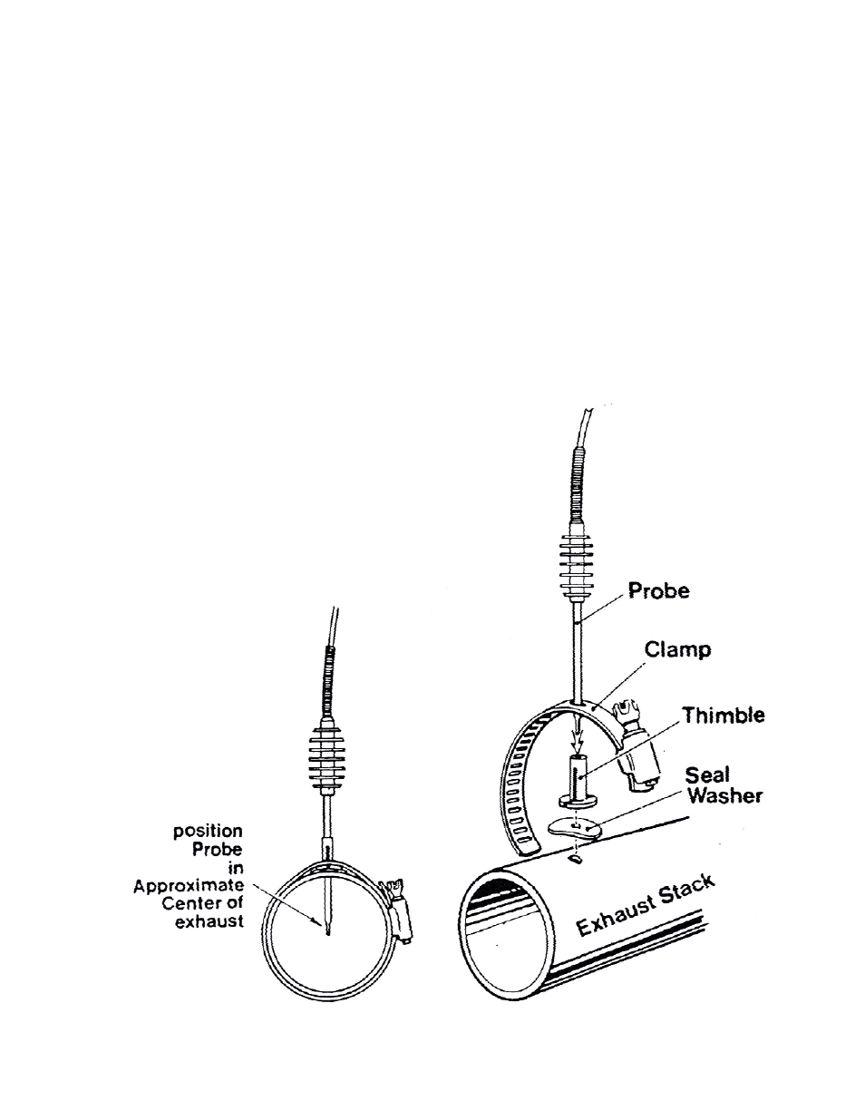
FIG-5 Probe Installation Instructions
The K/MM-ll1 Probe will fit an 1/8 (.125) to ¼ inch dia. hole
in the exhaust stack that is approximately
3 to 4 inches from the cylinder exhaust port. Installation is
extremely simple and requires no special tools or welding.
Assembly is accomplished by inserting the stainless steel
thimble thru the hole in the clamp, inserting the probe in
the thimble and applying the sealing washer between the
thimble and the exhaust stack in such a position that the
radius of the washer follows the curvature of the stack.
Insert the probe in the exhaust stack so that the tip of the
probe is in the approximate center of the exhaust stack. Try not
to go over center. Make certain that the slot in the thimble is
positioned LONGITUDINALLY with the length of the exhaust
stack or the probe will not lock firmly. Tighten the clamp firmly,
which will lock the probe thimble assembly and probe in
position.