Step 2, Step 3, The powerbridge in-wall extension is now energized – PowerBridge TSCK User Manual
Page 2
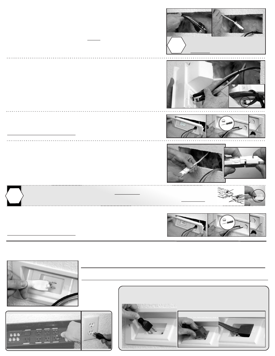
Step 2
Wall Installation
A) Begin at the upper PowerOUT location.
Drop or wall-fish audio video cables FIRST, to the PowerIN
location below.
REPEAT for PowerConnect cable with connector.
Step 3
Plug it in
Plug TV power supply cord in to PowerOUT and connect AV cables to TV.
Follow wall mount manufacture instructions, install TV on wall bracket.
Surge Protector
Plug supplied 6’ PowerConnect cord into PowerIN.
Plug other end into existing grounded outlet or surge protector.
Do not use another extension cord to extend the supplied cord.
To disconnect
PowerConnectors, push-in end of Locking Latch on the clear side of both connectors.
Press with finger tips at the same time pulling apart connectors to disconnect from Locking Tabs.
!
Locking Tab
Locking Latch
Plug in TV
Plug in Flat Angle Plug in the far right receptacle
Drop or wall-fish audio/video
cables within wall
BEFORE PowerConnect cable
!
B) Slide audio video cables through backside of CableGate.
Optional:
Cable zip-tie straps can be used to secure cables through CableHoops.
Allow for enough cable length out to connect to TV and AV equipment.
C) Slide PowerOUT panel into wall opening.
Use Flat-Blade screw driver to secure panel to wall.
Careful to not over-tighten.
D) At PowerIN location, connect both PowerConnect Cable
connectors together.
You should hear a click sound locking both connectors together.
Repeat step B with audio video cables.
E) Slide PowerIN panel into wall opening.
Use Flat-Blade screw driver to secure panel to wall.
Careful to not over-tighten.
The PowerBridge In-Wall Extension is now energized.
Existing
Outlet