Terms and conditions (for customer), Operation – Defi Racer Gauge 80 tachometer User Manual
Page 2
Maintenance & Check/Warranty & Servicing
■Warranty card・Terms and conditions
This product is delivered with this operation manual and a warranty card. Please read terms and conditions in
this manual thoroughly and keep the warranty card in a safe place. Failure to show this warranty will void the
warranty.
■Warranty period
Limited one year warranty. The warranty period starts at the date of retail purchase by the original end-user
purchase. Please confirm the warranty card is provided with the information of retail store where purchased.
Please refer to Limited Warranty for details.
■Inspection
Please ask the shop you purchased the product for inspection if any defect in product is suspected. We don't
accept the order of fixing because Defi products require installation and wiring to the vehicle. In case you cannot
go to the shop you purchased because of move-out or closure of shop, please ask the nearest Defi Distributor
listed in the Defi website.
※For a repair/inspection service, take the warranty card and customer contact information with you.
■Label
The label sticked on the product is for the product traceability. Do not peel it o�.
■Repairing
When a repair is necessary, we will return the inspection result report through the store to you. After receiving a
repair service request, we start repairing. Ask the store how much it costs and how long it takes to repair.
■Discarding the products
Please dispose products in accordance with disposal laws, state laws and local government. A recycle label on
the package indicates that the package is recyclable.
Except in the case of defects, we shall not be liable for any trouble including violation, accident or improper
wiring resulting from using this product.
The warranty does not cover any unauthorized repair performed or caused to be performed by the end user.
Such action can destroy or damage this product.
Terms and Conditions (for customer)
A. Limited Warranty
a. Our sole obligation to you after the sale of a product is to replace, without charge, the product or any
component thereof discovered to bee defective within a period of one (1) year from the purchasing
date(the "Warranty Period"). You accept sole responsibility for the proper assembly operation and
regular maintenance of the product. This limited warranty is void if any product is damaged by
accident, misuse, improper installation, or abuse, including tampering or damage in transit. Further,
this limited warranty is void if you sell or otherwise transfer a product to a third party, regardless of
whether the transfer takes place within the Warranty Period.
b. Out liability to you resulting from the sale of any product, including liability for any latent defects found
within the Warranty Period, shall not exceed the total purchase price paid for the product by you.
c. YOU UNDERSTAND AND AGREE THAT WE MAKE NO REPRESENTATIONS OR WARRANTIES OF
ANY KIND, EXPRESS OR IMPLIED AS TO ANY MATTER WHATSOEVER, INCLUDING THE
CONDITION OF THE PRODUCT OR ANY COMPONENT PARTS THEREOF, ITS
MERCHANTABILITY OR ITS FITNESS FOR ANY PARTICULAR PURPOSE AND YOU ACCEPT IT,
"AS IS," "WHERE IS."
d. You also understand that we are not granting any express warranties, other than those stated herein.
These include only those warranties enumerated in paragraph A. a. There are no other express
warranties granted anywhere in these terms and conditions of sale, and you understand and agree to
this fact as part of the bargained for exchange of this sale. Nowhere else, except as stated in this
paragraph, in this contract is there intended, by either party, for there to be any express warranties
granted to you.
e. EXCEPT AS OTHERWISE PROVIDED HEREIN, WE SHALL NOT BE LIABLE FOR DAMAGES,
INCLUDING SPECIAL, INCIDENTAL OR CONSEQUENTIAL DAMAGES WHETHER IN CONTRACT
OR IN TORT ARISING OUT OF OR IN CONNECTION WITH THE PERFORMANCE OF ANY
PRODUCT OR ANY COMPONENT PART THEREOF OR ITS USE BY YOU, AND WE SHALL NOT
BE LIABLE FOR ANY SPECIAL, INCIDENTAL OR CONSEQUENTIAL DAMAGES ARISING OUT OF
OR IN CONNECTION WITH YOUR USE OF THE PRODUCT.
f. The warranty on this product is void if the product is modified, changed, adjusted or damaged. This
product is to be used only in the ways for which it is designed and marketed for, any deviations from
the intended uses will void the warranty and will excuse any possible liability of ours.
g. You accept sole responsibility for the proper assembly, operation and regular maintenance of the
product. This limited warranty is void if the product is damaged, changed, altered, or modified by
accident, misuse, improper installation , or abuse, including tampering or damage in transit or while in
use. YOU HAVE MADE AN INDEPENDENT INVESTIGATION OF THE PURCHASED
COMPONENTS AND HAVE RELIED SOLELY ON YOU OWN INVESTIGATION, BARGAINING AND
JUDGMENT IN REFERENCE THERETO. YOU ACKNOWLEDGE THAT YOU ARE NOT RELYING
ON OUR SKILL OR JUDGMENT TO SELECT OR FURNISH GOODS SUITABLE FOR ANY
PARTICULAR PURPOSE IN PURCHASING OUR PRODUCTS, YOU HAVE NOT RELIED OR
ACTED UPON ANY REPRESENTATIONS OR WARRANTIES ON OUR PART NOT SPECIFICALLY
SET FORTH HEREIN.
h. This limited warranty gives you specific legal rights. You may also have other rights which vary from
state to state. Some states do not enforce contractual limitations on how long an implied warranty
lasts, when an action may be brought, or the exclusion or limitation of incidental or consequential
damages, so the above limitations or exclusions may not apply to you.
B. Modification Strictly Prohibited
You understand and agree that any modification whatsoever , of the product, is strictly prohibited. You
also agree not to modify the product in any manner regardless of whether such modification is
material or immaterial. You also acknowledge that any modification of the product will void your
limited warranty and bar you from any recovery or any remedy in a court of law or equity. Modification
is strictly forbidden unless expressly authorized by our prior written approval. You agree not to make
any modifications to the product and agree not to use any parts, components, or accessories in
connection with the installation and use of the product that are not authorized and approved by us.
C. Indemnity and Release
a. You understand and agree that many factors beyond our control affect the operational safety of the
product, including but not to limited to the installation of the product according to the instructions
provided with the product.
b. You also understand and agree that the installation of the product may involve the use of tools,
equipment and construction methods which may present safety hazards which are beyond our
control. You also understand and agree that the use of some of our products may create hazards and
lower your ability to control your vehicle.
c. You agree, as part of the bargained for exchange, to protect, indemnify, save harmless and release
us, our authorized agents, employees, officers, directors and shareholders from and against all
liabilities, obligations, claims, damages, penalties, causes of action, costs and expenses, imposed
upon or incurred by or asserted against us or any assignees of ours, by you or any third party by
reason of the occurrence or existence (or alleged occurrence or existence) of any use, installation,
assembly, possession or operation of the product, any loss, damage or destruction of the product as
of and after delivery(a "casualty occurrence"), and any other act or event relating to or caused by the
product, including but not limited to, consequential or of the terms and conditions hereof, or any and
all liability for property loss or damage, or any and all damage resulting from death or personal
injuries, including loss of services which any person may sustain on account of, arising out of, or in
connection with any use, maintenance, possession or operation of the product. In the event that any
action, suit or proceeding is brought against us or any of our authorized agents, employees, officers,
directors or shareholders by reason of any such occurrence, you will, upon our request and at your
expense, resist and defend such action, suit or proceeding or cause the same to be resisted and
defended by counsel designated and approved by us.
LIMITED PRODUCT WARRANTY AND LIMITED PRODUCT LIABILITY
※If the problem is not solved after the remedies mentioned above are tried:
⇒Ask the installation personnel or the shop you purchased the gauge for inspection.
⇒Purchase new parts for replacing wear-out parts .
Racer Gauge Tachometer
Φ80 Operation Manual
■
Issue First edition: September, 2011
■
Manufacturer
Nippon Seiki Co., Ltd.
■
Contact Information Nippon Seiki Co., Ltd. Defi Business Division
【Address】 190-1 Fujihashi 1-chome, Nagaoka-shi, Niigata 940-2141 JAPAN
【URL】 http://www.defi-shop.com/
Patent pending
PAT. 3284535 PAT. 3365604 PAT. 4737376
Made in Japan
Operation
(for customer and installation personnel)
(for customer and installation personnel)
3. Setup
3. Setup
4.Motion mode
4.Motion mode
2. Switch operation list
2. Switch operation list
Be sure to make preparatory settings. The unit will not operate properly without the settings being made.
Set up while the vehicle is stationary.
Confirmation
In the real mode, the mode changed to the setup mode by pressing
▲switch and ▼switch at the same
time for more than 2 seconds. In the setup mode, the peak and warning LEDs in the gauge blinks
alternately. And the gauge pointer points the number of cylinders. The buzzer bleeps. Set up the
number of cylinders and the buzzer on/off in the setup mode. The mode returns to the real mode
automatically when any switch is not pressed for more than 5 seconds.
In the setup mode, the setup of the number of cylinders changes every time
▼switch is pressed(4→3→
2
→1→8→6→5→4→・・・(repeat). Match the number on the gauge dial and the number of cylinders of
your vehicle.
The mode returns to the real mode automatically when any switch is not pressed for more than 5
seconds.
Set whether to turn the buzzer on or off when warning SET2 is exceeded.
In the setup mode, the buzzer is turned on/off by pressing
▲switch. If the buzzer is set on, it bleeps
(short beeps) in time with blinking of the peak and warning LEDs. If the buzzer is set off, it does not
sound.
If the buzzer is set on, it feeps (a long beep) when the RPM exceeds the warning SET2 in the real
mode. If the buzzer is set off, it does not sound.
The mode returns to the real mode automatically when any switch is not pressed for more than 5
seconds.
※The buzzer sounds when switches are pressed. It cannot be turned off.
Two warning RPMs can be set at SET1 and SET2. Set the SET2 RPM higher than the SET1 RPM. The factory setting is
at 6000rpm(SET1) and 7000rpm(SET2). Change the RPMs as you like.
※Even if the battery is disconnected, the setting is not cleared.
In the real mode, the mode changes to the warning setup mode SET1 if
▼switch is pressed for more
than 2 seconds. In the warning setup mode SET1, the warning LED blinks as follows:
In the real mode, the mode changes to the warning setup mode SET2 if
▲switch is pressed for more
than 2 seconds. In the warning setup mode SET2, the warning LED blinks as follows:
To raise the set RPM of the warning, press
▲switch. Every time ▲switch is pressed, the set RPM is
raised in degree. If
▲switch is pressed long, the set RPM is raised faster. To lower the set RPM of the
warning, press
▼switch. Every time ▼switch is pressed, the set RPM is lowered in degree. If ▼switch is
pressed long, the set RPM is lowered faster.
The mode returns to the real mode automatically when any switch is not pressed for more than 5 seconds.
※The range of the warning RPM which can be set is from 500rpm is to the maximum scale RPM.
※Set the lower RPM than the warning SET2 RPM.
If the warning SET1 RPM is set higher than the SET2 RPM:
→The warning SET2 RPM is changed to the same RPM as the SET1 RPM.
Ex) If the SET2 RPM is set at 6000rpm, it is changed to 7000rpm when the SET1 RPM is changed to 7000rpm.
To raise the set RPM of the warning, press
▲switch. Every time ▲switch is pressed, the set RPM is
raised in degree. If
▲switch is pressed long, the set RPM is raised faster. To lower the set RPM of the
warning, press
▼switch. Every time ▼switch is pressed, the set RPM is lowered in degree. If ▼switch is
pressed long, the set RPM is lowered faster.
The mode returns to the real mode automatically when any switch is not pressed for more than 5 seconds.
※The range of the warning RPM which can be set is from 500rpm is to the maximum scale RPM.
※Set the higher RPM than the warning SET1 RPM.
If the warning SET2 RPM is set lower than the SET1 RPM:
→The warning SET1 RPM is changed to the same RPM as the SET2 RPM.
Ex) If the SET1 RPM is set at 7000rpm, it is changed to 6000rpm when the SET2 RPM is changed to 6000rpm.
Set up the number of cylinders and buzzer. The factory setting of the number of cylinders is 4. If the gauge is installed in
a vehicle which the number of cylinders is not 4, change the number as follows. The factory setting of the buzzer is ON.
※Even if the battery is disconnected, the setting is not cleared.
The gauge performs the opening mode when the ignition key is turned on and performs the closing mode when the ignition
key is turned off.
※The brightness is at the maximum level during the opening mode regardless of the dimmer control setup.
※In case any other Defi-Link products are already installed in the vehicle, supply power from the same source as the
Defi-Link products to perform the opening and closing mode at the same time. If the power is supplied from the different
source from the others, gauges may not perform the opening and closing mode at the same time.
①Opening and closing mode
①Opening and closing mode
The gauge pointer points at the RPM in real time. The maximum RPM is recorded during this mode.
In the real mode, when the RPM exceeds the set warning RPMs, the warning LED and the indicator light up/blink as
follows.
②Real mode
②Real mode
③Warning mode
③Warning mode
In the real mode, the peak LED lights up and the mode changes to the peak mode by pressing
▲switch.
The recorded maximum(peak) RPM is displayed during the peak mode. Every time the maximum RPM
is updated, it is recorded. The peak mode returns to the real mode by pressing
▲switch again.
In the peak mode, the peak LED blinks and the maximum RPM is reset by pressing
▲switch. Then the
peak mode returns to the real mode.
※Even if the battery is disconnected, the recoded maximum RPM is not cleared.
In the real mode, the brightness of the gauge illumination is controlled by pressing
▼switch. There are
5 stages for the daytime and 6 stages for the nighttime. The brightness can be decreased/increased
with the vehicle lights switched on/off.
※Even if the battery is disconnected, the set level is not cleared.
※The brightness level does not change even if ▲switch is pressed. The mode changes to the peak mode.
④Peak mode
④Peak mode
⑤Dimmer control
⑤Dimmer control
②Warning setup mode
②Warning setup mode
①Setup mode
①Setup mode
Upper switch(
▲/SET-2/PEAK) → ▲switch or
Lower switch(
▼/SET-1/PEAK RESET) → ▼switch or
Two switches are expressed in this section as follows.
Condition
Possible Cause
Corrective Action
○Wiring of the power supply wire is
improper.
○The locks of the solderless connectors
are not locked tightly.
○Does not operate.
○Power is not supplied.
○Check wirings of +B, IGN, GND as per
instructions in this manual.
○Check the lock of the solderless connectors.
○Wiring of the tachometer signal is wrong.
○Setting of the number of cylinders is
wrong.
○The RPM is not displayed
correctly.
○Check wiring as per instructions in this manual.
○Check the number of cylinders as per instructions
in this manual.
○Originally equipped gauges commonly
indicate up to 10% higher RPM.
○The RPM gauge indicates is
a little lower than that of
originally equipped gauge.
○Check if the difference is up to 10%. This
product is designed emphasizing accuracy and
should have little error margin. If the difference
is bigger than 10%, check the setup of the
number of cylinders.
○The battery wiring is wrong.
○The fuse of the power supply wire is
blown out.
○Does not carry out the
closing mode.
○Check wiring of +B as per instructions in this
manual.
○Make sure the wiring is not touched on the
vehicle body and then change the fuse.
○Check the solderless connector of battery wiring.
○The warning set1 RPM is set higher than
the warning set2 RPM or the warning
set2 RPM is set lower than the warning
set1 RPM.
○The warning LED lights up
at the different RPMs than
set RPMs.
○When the warning set1 RPM is set at the higher
RPM than the warning set2 RPM or when the
warning set2 RPM is set at the lower RPM than
the warning set1 RPM, set RPMs are changed
automatically. Refer to Operation section.
○The illumination is in the brightest level of
nighttime mode.
○Wiring of the power supply wire is
improper.
○The illumination brightness
doesn't change by turning
on/off the vehicle
illumination.
○Check if the illumination is in the brightest level of
nighttime mode and press
▼switch.
○Check wiring of ILM as per instructions in this
manual.
○Check the lock of the solderless connectors.
○The pointer moves during transfer.
○The needle pointer is not
downward before the
electricity is turned on.
○It is an inherent property of the stepping motor.
The pointer may move when a slight impact is
made to the gauge. Check if it operates normally
by turning on and off the electricity and the pointer
points zero after the ignition is turned off.
【A】Setup number of cylinders
【B】Setup buzzer
【A】Warning setup mode − SET1
【B】Warning setup mode − SET2
Higher
■→■→■→■→■
■ ■→■→■→■→■
Brighter
Brightness level
Darker
Bleep (short beeps)
In real mode
To peak mode
In real mode
Returns to real mode
Peak LED blinks and recorded maximum RPM is reset.
Then pointer points at 0rpm and mode returns to real mode.
raise
lower
raise
lower
Peak LED
Warning LED
Buzzer
The warning LED is on. The buzzer is off. The indicator is on in green.
The warning LED blinks. The buzzer feeps (a long beep). The indicator is on in red.
※The buzzer does not sound if the buzzer is set off in the setup mode.
【Scene B】When the RPM is higher than the warning SET1 RPM
【Scene C】When the RPM is higher than the warning SET2 RPM
The warning LED is off. The buzzer is off. The indicator is off.
【Scene A】When the RPM is lower than the warning SET1 RPM
Engine speed
Daytime
(vehicle lights off)
Nighttime
(vehicle lights on)
Dimmer
control
Peak mode
Setup mode
Returns to the real mode Returns to the real mode Returns to the real mode
Warning setup mode
SET1
Warning setup mode
SET2
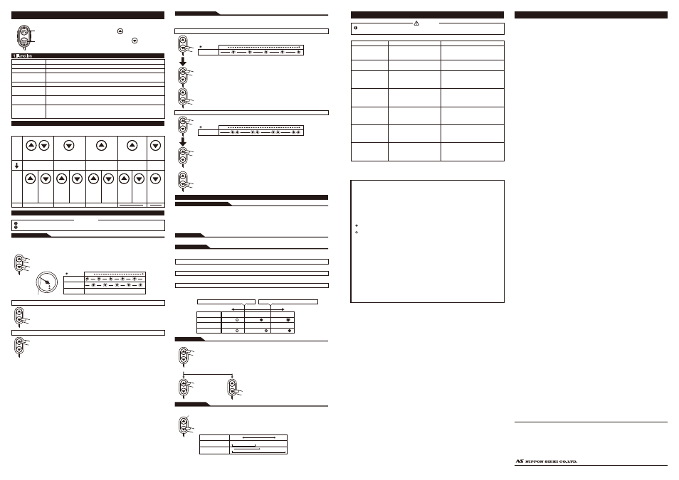
The following is the list of operations with switches. In the setup mode and the warning setup mode, the mode changes to
the real mode when any switch is not pressed for more than 5 seconds.
1.Function
1.Function
Number of cylinder setup
Warning setup
Buzzer setup
Opening/
Closing mode
Real mode
Warning mode
Peak mode
Dimmer control
To Set up the number of cylinders according to your vehicle
To Set up the RPMs of warning. Two points(SET1 and SET2) can be set.
To Set up the buzzer ON/OFF of warning SET2.
When the ignition is turned on/off, the opening and closing motion is played by using the
illumination of the gauge and movement of the pointer.
Displays the RPM in real mode during driving and idling.
Informs the RPM exceeds the set warning RPMs by the warning LED, the buzzer, and the
indicator.
Displays the maximum RPM recorded during driving. The maximum RPM is always
recorded in the real and peak modes. It can be reset.
Controls the brightness of the gauge illumination.
There are 5 stages of brightness for the
daytime and 6 stages for the nighttime. The brightness can be decreased/increased with the
vehicle lights switched on/off.
5sec later
The pointer points the number of cylinders.
Time
LED blinking
Warning LED
Time
Warning LED
Time
Lower
Scene
Warning LED
Buzzer
Indicator
【
Scene A】
Off
Off
Off
【
Scene B】
On
Off
On(green)
【
Scene C】
Blink
Feep(a long beep)
On(red)
Warning SET1
:Factory setting 6000rpm
Warning SET2
:Factory setting 7000rpm
unused
press long
press
long
press
long
Real
mode
Operation
after the
mode is
changed
Press 2 switches at the same
time for more than 2 seconds.
Press
▼ switch for
more than 2 seconds.
Press
▲ switch for
more than 2 seconds.
Press
▲ switch.
Press
▼ switch.
Setting of
number of
cylinders
Buzzer
on/off of
Warning
SET2
Raise setting
To raise
faster, push
long.
Lower setting
To lower
faster, push
long.
Raise setting
To raise
faster, push
long.
Lower setting
To lower
faster, push
long.
Returns to
real mode
Peak RPM
is reset and
returns to
real mode.
Brightness
changes every
time switch is
pressed.
LED blinking
LED blinking
If operation of the product seems unusual, inspect the product to confirm that there is no malfunction. If an
operational problem has occurred, it could result in an accident.
Warning
※In addition to a general inspection of the product, use the following table to confirm proper operation of the unit.
Trouble Shooting(for customer and installation personnel)