Defi ADVANCE BF (except tachometer) User Manual
Page 2
→
↑
→
(provided with commercial parts)
(provided with
commercial parts)
OIL PRESS.
(DF081, 089, 102 series)
■Components
Sensor wire 3m
(10ft) 1pc
Meter wire 0.25m
(10”) 1pc
Gauge 1pc
Pressure sensor
(1/8PT) 1pc
Meter cup 1pc
*Regular position
bezel 1pc(CR only)
Operation manual (this sheet) and warranty card are included other than the parts listed above. Keep them at hand.
*A regular position bezel is not included in ADVANCE BF gauge unit. (Sold separately: PDF08607G)
Black
3pins
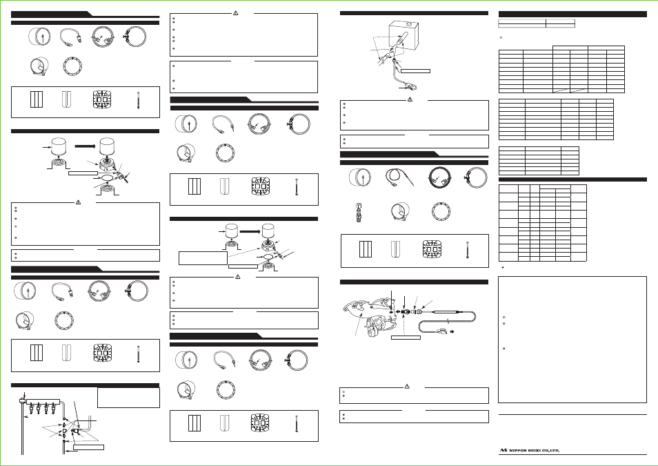
■How to attach pressure sensor (Use a commercial sensor attachment.)
Engine
Engine
Sensor attachment
(commercially available)
O ring
Sensor
To sensor wire
Thread size 1/8PT
Detach the original
element.
Wind Teflon tape.
Be sure not to twist.
The thread size of the pressure sensor is 1/8PT. Use a sensor attachment of 1/8PT.
Tighten the sensor into the sensor attachment and then connect it to the sensor wire.
Be sure the sensor wire is not twisted when installing the sensor. The sensor wire will be cut.
Oil spills by the installation work. Please replenish the engine with oil. The engine might overheat
when oil is too little.
To avoid oil leaks by installing of the sensors, use Teflon tape. Before driving, inspect oil blocks for
leaks. Leaks could cause a fire or damage the engine.
Do not install the sensor near oil pump. Do not install the sensor to pressure switch directly. Failure to
do so could damage the sensor because the pressure pulsation is too big and exceed three times
full-scale momentarily.
To avoid the damage of the sensor wire, please fix the waterproof connector on the vehicle body and
do not bend the sensor wire near the sensor.
Warning
Confirmation
FUEL PRESS.
(DF082, 090, 103 series)
■Components
Sensor wire 2.5m
(8 1/5ft) 1pc
Meter wire 0.25m
(10”) 1pc
Gauge 1pc
Pressure sensor
(1/8PT) 1pc
Meter cup 1pc
*Regular position
bezel 1pc(CR only)
Red
3pins
Operation manual (this sheet) and warranty card are included other than the parts listed above. Keep them at hand.
*A regular position bezel is not included in ADVANCE BF gauge unit. (Sold separately: PDF08607G)
Mounting bracket set
Double sided
tape 1pc
Buffer
1pc
Mounting
bracket 1pc
M4 bolt, nut,
washer 1pc
■How to attach pressure sensor (Use a commercial three-way joint and hose unions.)
Fuel pressure regulator
Three-way joint
(commercially available)
Fuel return pipe
(low pressure)
Hose union
(commercially
available)
Fuel feed pipe (high pressure)
Fix tightly with clamps.
(commercially available)
Wind Teflon tape.
Sensor
To sensor wire
Thread size 1/8PT
Be sure not to twist.
*Cut the fuel feed pipe and install hose
unions.
*If the material used for the inner surface
of fuel feed pipe is resin, a hose union
may not be fixed. Check the material
before cutting the fuel feed pipe.
Be sure the sensor wire is not twisted when installing the sensor. The sensor wire will be cut.
Before cutting the fuel feed pipe, be certain to remove the gas cap to relieve any pressure built up in the
fuel tank.
When cutting the fuel feed pipe, be certain to discharge static electricity. Otherwise, there is a possibility
of the ignition in gasoline.
Wear glasses to protect eyes when cutting the fuel filter pipe.
To avoid fuel leaks during installation of the sensor, use Teflon tape. Attach hose connection and fuel
feed tubing with clamps. Inspect pipes and hose connections for leaks before driving.
To avoid the damage of the sensor wire, please fix the waterproof connector on the vehicle body and
do not bend the sensor wire near the sensor.
The sensor must be installed on the feed (high pressure) pipe side between the fuel tank and the
fuel pressure regulator.
*It is not possible to obtain accurate fuel pressure from the return (low pressure) side at the rear of the
fuel pressure regulator.
The thread size of hose unions and the three-way joint need to be 1/8PT. Use hose unions and a
three-way joint of 1/8PT.
Tighten the sensor into the sensor attachment and then connect it to the sensor wire.
Warning
Confirmation
OIL TEMP.
(DF083, 091, 104 series)
■Components
Gauge 1pc
Temperature sensor
(1/8PT) 1pc
Sensor wire 3m
(10ft) 1pc
Red
2pins
Meter wire 0.25m
(10”) 1pc
Meter cup 1pc
*Regular position
bezel 1pc(CR only)
Operation manual (this sheet) and warranty card are included other than the parts listed above. Keep them at hand.
*A regular position bezel is not included in ADVANCE BF gauge unit. (Sold separately: PDF08607G)
Mounting bracket set
Double sided
tape 1pc
Buffer
1pc
Mounting
bracket 1pc
M4 bolt, nut,
washer 1pc
Engine
Sensor attachment
(commercially available)
O ring
Sensor
Detach the original element.
Wind Teflon tape.
Be sure not to twist.
■How to attach temperature sensor (Use a commercial sensor attachment.)
Do not put the sensor in the side
hole. The depth of the hole for the
sensor must be more than 30mm.
Thread size 1/8PT
Engine
To sensor wire
The thread size of the temperature sensor is 1/8PT. Use a sensor attachment of 1/8PT.
The depth of the hole for the sensor must be more than 30mm.
Tighten the sensor into the sensor attachment and then connect it to the sensor wire.
Be sure the sensor wire is not twisted when installing the sensor. The sensor wire will be cut.
Oil spills by the installation work. Please replenish the engine with oil. The engine might overheat
when oil is too little.
To avoid oil leaks by installing of the sensors, use Teflon tape. Before driving, inspect oil blocks for
leaks. Leaks could cause a fire or damage the engine.
To avoid the damage of the sensor wire, please fix the waterproof connector on the vehicle body and
do not bend the sensor wire near the sensor.
Warning
Confirmation
WATER TEMP.
(DF084, 092, 105 series)
■Components
Gauge 1pc
Temperature sensor
(1/8PT) 1pc
Sensor wire 3m
(10ft) 1pc
Pink
2pins
Meter cup 1pc
*Regular position
bezel 1pc(CR only)
Operation manual (this sheet) and warranty card are included other than the parts listed above. Keep them at hand.
*A regular position bezel is not included in ADVANCE BF gauge unit. (Sold separately: PDF08607G)
Mounting bracket set
Double sided
tape 1pc
Buffer
1pc
Mounting
bracket 1pc
M4 bolt, nut,
washer 1pc
Meter wire 0.25m
(10”) 1pc
Radiator
Attach tightly with clamps.
(commercially available)
Wind Teflon tape.
Sensor
→To sensor wire
Thread size 1/8PT
Be sure not to twist.
*Cut the upper hose and connect the
sensor attachment between hoses.
Upper hose
Sensor attachment
(commercially available)
Be sure the sensor wire is not twisted when installing the sensor. The sensor wire will be cut.
Coolant spills by the installation work. Please replenish the engine with coolant and bleed the air
from the system, or the engine might overheat.
To avoid water leaks during installation of the sensors, use Teflon tape. Attach the sensor
attachment and upper hose with clamps. Inspect hose connections for leaks before driving.
To avoid the damage of the sensor wire, please fix the waterproof connector on the vehicle body and
do not bend the sensor wire near the sensor.
The thread size of the temperature sensor is 1/8PT. Use a sensor attachment of 1/8PT.
Tighten the sensor into the sensor attachment and then connect it to the sensor wire.
Confirmation
Warning
■How to attach temperature sensor (Use a commercial sensor attachment.)
■Components
Gauge 1pc
Exhaust temperature
sensor 1pc
Sensor wire 2.5m
(8 1/5ft) 1pc
Fitting (1/8PT) 1pc
Black
2pins
EXHAUST TEMP.
(DF085, 093, 106 series)
Meter wire 0.25m
(10”) 1pc
Meter cup 1pc
*Regular position
bezel 1pc(CR only)
Operation manual (this sheet) and warranty card are included other than the parts listed above. Keep them at hand.
*A regular position bezel is not included in ADVANCE BF gauge unit. (Sold separately: PDF08607G)
Mounting bracket set
Double sided
tape 1pc
Buffer
1pc
Mounting
bracket 1pc
M4 bolt, nut,
washer 1pc
Thread size 1/8PT
Exhaust manifold
Make a threaded screw
hole (1/8PT).
Sensor wire
Fitting(b)
Bushing
Exhaust temperature sensor
Fitting(a)
The thread size of the fitting is 1/8PT. Make a threaded screw hole of 1/8PT.
Tighten the sensor into the sensor attachment and then connect it to the sensor wire.
Confirmation
To avoid personal injury, do not install the exhaust temperature sensor while the engine is hot.
When making a hole, make sure no chip remains in the exhaust pipe or turbine. It may result in
damage to the engine, exhaust pipe, or turbine.
Warning
1) Make a 1/8PT threaded screw hole in the exhaust manifold pipe. (Weld if the pipe wall thickness is not
enough)
2) Dismantle the fitting. Do not crush the bushing inside the fitting.
3) Tighten the fitting(a) to the hole of the exhaust manifold.
4) Pierce the sensor through the fitting(b) and the busing.
5) Insert the edge of the sensor into the fitting(a) and position it at the center of the exhaust pipe.
6) Tighten the fitting(b).
■How to attach exhaust temperature sensor for exhaust temperature
Please refer to the Defi-Link ADVANCE Control unit operation manual for installation,
operation, troubleshooting, repair parts, optional parts, and terms and conditions.
Defi-Link Meter ADVANCE CR & ADVANCE BF Operation Manual
■
Issue First edition: August, 2013
■
Manufacturer Nippon Seiki Co., Ltd.
■
Contact Information Defi, Nippon Seiki Co., Ltd.
[Address] 190-1 Fujihashi 1-chome, Nagaoka-shi, Niigata 940-2141 JAPAN
[URL] http://www.defi-shop.com/
PAT. 3019067 PAT. 3019939
Mounting bracket set
Double sided
tape 1pc
Buffer
1pc
Mounting
bracket 1pc
M4 bolt, nut,
washer 1pc
Gauge
Default
setting
Unit
Setting range
Lighting
condition
Minimum Maximum
Turbo
100
kPa
-100
200
Set value
and above
14.5
PSI
-14.5
29
In-Mani Press
10
kPa
-100
200
Set value
and above
1.45
PSI
-14.5
29
Tachometer
7000
RPM
300
11000
Set value
and above
Oil press
120
kPa
0
1000
Set value
and below
17.5
PSI
0
145
Fuel press
150
kPa
0
600
Set value
and below
21.8
PSI
0
87
Oil temp
125
℃
0
150
Set value
and above
257
°
F
32
302
Water temp
105
℃
0
150
Set value
and above
221
°
F
32
302
Exhaust temp
850
℃
0
1100
Set value
and above
1562
°
F
32
2010
Maintenance & Check/Warranty & Servicing
■Warranty card・Terms and conditions
This product is delivered with this operation manual and a warranty card. Please read terms and conditions in this
manual thoroughly and keep the warranty card in a safe place. Failure to show this warranty will void the warranty.
■Warranty period
Limited one year warranty. The warranty period starts at the date of retail purchase by the original end-user
purchase. Please confirm the warranty card is provided with the information of retail store where purchased. Please
refer to Limited Warranty for details.
■Inspection
Please ask the shop you purchased the product for inspection if any defect in product is suspected. We don't accept
the order of fixing because Defi products require installation and wiring to the vehicle. In case you cannot go to the
shop you purchased because of move-out or closure of shop, please ask the nearest Defi Distributor listed in the
Defi website.
For a repair/inspection service, take the warranty card and customer contact information with you.
Please conduct periodic inspections by Defi through a shop which sells Defi products or Defi’s official distributor
every five years. Inspection is available at an additional cost. In the case you purchase used products or used
vehicles with products of Defi, please have an inspection by Defi as well before using them.
■Label
The label sticked on the product is for the product traceability. Do not peel it off.
■Repairing
When a repair is necessary, we will return the inspection result report through the store to you. After receiving a
repair service request, we start repairing. Ask the store how much it costs and how long it takes to repair.
■Discarding the products
Please dispose products in accordance with disposal laws, state laws and local government. A recycle label on the
package indicates that the package is recyclable.
Except in the case of defects, we shall not be liable for any trouble including violation, accident or improper
wiring resulting from using this product.
The warranty does not cover any unauthorized repair performed or caused to be performed by the end user.
Such action can destroy or damage this product.
DF07801
DF07802
DF07901
DF07902
DF08001
DF08002
DF08101
DF08102
DF08201
DF08202
DF08301
DF08302
DF08401
DF08402
DF08501
DF08502
DF08601
DF08602
DF08701
DF08702
DF08801
DF08802
DF08901
DF08902
DF09001
DF09002
DF09101
DF09102
DF09201
DF09202
DF09301
DF09302
DF09403
DF09404
Φ 52 series
■CR gauges (SI models)
Φ 60 series
Lineup (for customer)
Product Name
Product No.
Defi-Link ADVANCE Control unit
DF07703
Defi-Link Meter ADVANCE CR and ADVANCE BF need to be used with the advance control unit.
One advance control unit can control up to 7 gauges.
Do not connect more than one gauge of the same variety. (Ex. You can NOT connect 2 turbo gauges together.)
*In-Mani Press is an abbreviation of Intake Manifold Pressure.
Product name
Turbo2.0
Turbo1.2
In-Mani Press *
Oil Press
Fuel Press
Oil Temp
Water Temp
Exhaust Temp
Tachometer
■BF gauges Φ 60 series (SI models)
Product name
Display range
White Model Amber Red Model
Turbo2.0
Turbo1.2
In-Mani Press *
Oil Press
Fuel Press
Oil Temp
Water Temp
Exhaust Temp
Tachometer
DF09901
DF10001
DF10101
DF10201
DF10301
DF10401
DF10501
DF10601
DF10704
DF09902
DF10002
DF10102
DF10202
DF10302
DF10402
DF10502
DF10602
DF10705
Blue Model
DF09903
DF10003
DF10103
DF10303
DF10403
DF10503
DF10603
DF10203
DF10706
-100∼ +200kPa
-100∼ +120kPa
-100∼ +20kPa
0 ∼ 1000kPa
0 ∼ 600kPa
50 ∼ 150℃
20 ∼ 120℃
200 ∼ 1100℃
0 ∼ 9000rpm
Display range
-100∼ +200kPa
-100∼ +120kPa
-100∼ +20kPa
0 ∼ 1000kPa
0 ∼ 600kPa
50 ∼ 150℃
20 ∼ 120℃
200 ∼ 1100℃
0 ∼ 9000rpm
■BF gauges Φ 2 3/8” series (USDM models)
Product name
Display range
Amber Red Model
Boost
Oil Press
Fuel Press
Oil Temp
Water Temp
Exhaust Temp
DF09904
DF10204
DF10304
DF10404
DF10504
DF10604
-30inHg∼ +29PSI
0 ∼ 145PSI
0 ∼ 87PSI
122 ∼ 302 °F
68 ∼ 248 °F
392 ∼ 2010 °F
White Dial
Black Dial
White Dial
Black Dial
■ Factory default settings of warning values