Jammin Pro StudioMix 10 User Manual
Page 6
1.2 The user’ s manual
The user’ s manual is designed to give you both an overview of the controls, as well as detailed information
on how to use them.
1.3.1 Shipment
1.3 Before you get started
Your mixing console was carefully packed in the factory to guarantee safe transport. Nevertheless,
we recommend that you careful examine the packing and its contents for any signs of physical damage.
Which may have occurred during transit.
If the unit is damaged, please do NOT return it to us, but notify your dealer and the shipping
company immediately, otherwise claims for damage or replacement may not be granted.
1.3.2 Initial operation
Be sure that there is enough space around the unit for cooling purposes and to avoid over-heating please
do not place your mixing console on high-temperature devices such as radiators or power amps. The
console is connected to the mains via the supplied cable. The console meets the required safety standards.
Blown fuses must only be replaced by fuses of the same type and rating.
never connect the ME to the power supply unit when the latter is connected to the mains! First
connect the power supply unit to the console, then connect the power supply unit to the mains.
the block diagram supplied with the mixing console gives you an overview of the connections
between the inputs and outputs, as well as the associated switches and controls.
For the moment, just try and trace the signal path from the microphone input to the FX send connector,
Do not be put off by the huge range of possibilities; it is easier than you thank! if you look at quickly familiarize
yourself with your mixing console and you will soon be making the most of all its many possibilities.
3
to assure optimal protection of your ME during use or transports, we recommend utilizing a
carrying case.
Please always use the original packing to avoid damage due to storage or shipping.
Never let unsupervised children play with the ME or with its packaging.
Please dispose of all packaging materials in an environmentally-fiendly fashion.
▲
distribution to one or several recording tracks, power amp(s), control room and 2-track outputs.
Signal distribution: Summing of signals to the aux sends for effects processing and monitor mix,
▲
stereo field, level control of the total mix to match the recording devices/crossover/power
amplifier(s). All other mixer functions can be included in this main function.
Mix: Setting the volume level, frequency distribution and positioning of the individual signals in the
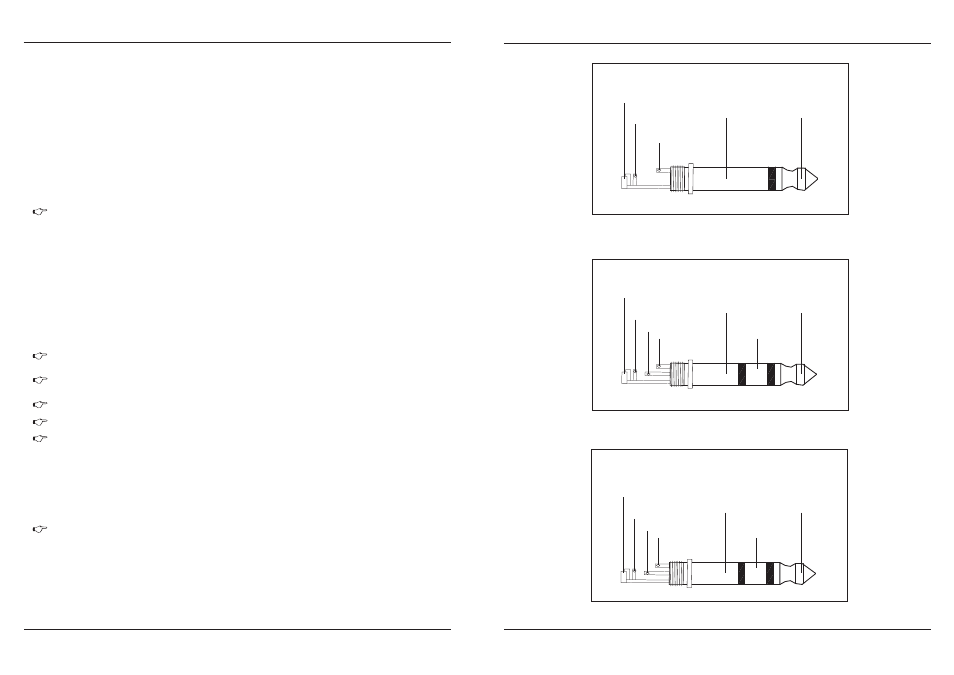
The foot switch connects the two poles momentarily
strain relief clamp
sleeve
tip
sleeve
tip
ground shield
signal
For connection of balanced and unbalanced plus,
rig and sleeve have to be bridged at the stereo plug
Headphones connection
with 1/4" TRS connector
strain relief clamp
sleeve
tip
sleeve
tip
ground shield
left signal
Fig. 4.4: Stereo plug for headphones connection
Fig. 4.3: 1/4"
stereo plug
Fig. 4.2: 1/4"mono plug
ring
right signal
ring
strain relief clamp
sleeve
tip
sleeve
tip
ground shield
hot (+ ve)
ring
cold (- ve)
ring
Balanced use of
1/4"T
RS connector
Unbalanced use of
1/4"T
RS connector
16