Rubicon Express RE7142 User Manual
Page 4
RE7122-RE7142b Page 4 of 5
D. Install the new coil springs with isolators at the top and raise the axle just enough to keep the springs and isolators in place.
Rear Upper Cam bolt installation
A.
One side at a time remove the factory bolt that attaches the upper control arm to the axle.
B.
Locate the indented marks around the square hole in the bracket to be removed. (Photo 2)
C.
Using a punch, hammer, and a receiving cup such as a socket that fits between the mounts knock out the tabs to
create elongated holes. If the tabs will not knock out with a couple hits of the punch, it will be necessary to use a burr
type cutter to elongate the holes.
D.
Install the cam bolt assemblies with one washer on each side of the bracket between the locating ears. Rotate the bolt
into the center portion of the slot and tighten the nut so the bolt will not spin but not fully tight at this time.
Rear bump pads, track bar bracket and factory track bar
A. Install the two bump stops on the axle with the supplied 3/8” bolts and lock nuts.
B. With the axle properly supported remove the driver’s side rear lower control arm from the axle this will allow for easier
access when installing the track bar bracket.
C. Place the new track bar bracket over the factory track bar mounting point on the axle while aligning the two 3/8” holes on
the back side of the lower control arm bracket. Loosely install the two 3/8” bolts, washers, and nuts thru the lower control
arm bracket and track bar bracket.
D. Install the 9/16x3.5” bolt thru the factory track bar location being sure to use the supplied spacer to keep the factory
bracket from collapsing. Tighten the two 3/8” bolts to 35 ft/lbs then tighten the 9/16” bolt to 90 ft/lbs.
E. Using the supplied 9/16x3” install the factory track bar into the new bracket. Install the nut on the back side near the coil
spring but do not tighten at this time. (Photo 4)
F. Reinstall the lower control arm to the axle mounting point and tighten the bolt.
Rear sway bar links, brake line extensions, and shocks
A. Install the supplied links (RE1157). Install the drivers side link to the outside of the sway bar and lower axle mounting point.
(Photo 4) drivers side shown
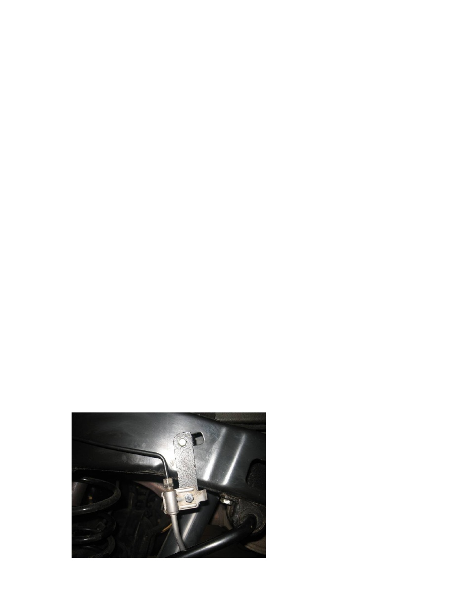
B. Install the supplied brake line extension brackets to the frame with the factory hardware. Use the supplied hardware to
reattach the brake line bracket to the lowering bracket (photo 5)
C. Install new shock absorbers. (sold separately)
PHOTO # 5