Rubicon Express RE7200 SERIES User Manual
Page 5
B.
Adjust front upper control arms’ length to an initial setting of 15-7/8” from bolt center to bolt center. Install front upper arms’
rubber bushing end into the welded on bracket of the lower arms with supplied hardware. The upper arms will be used to adjust
final caster and pinion angle.
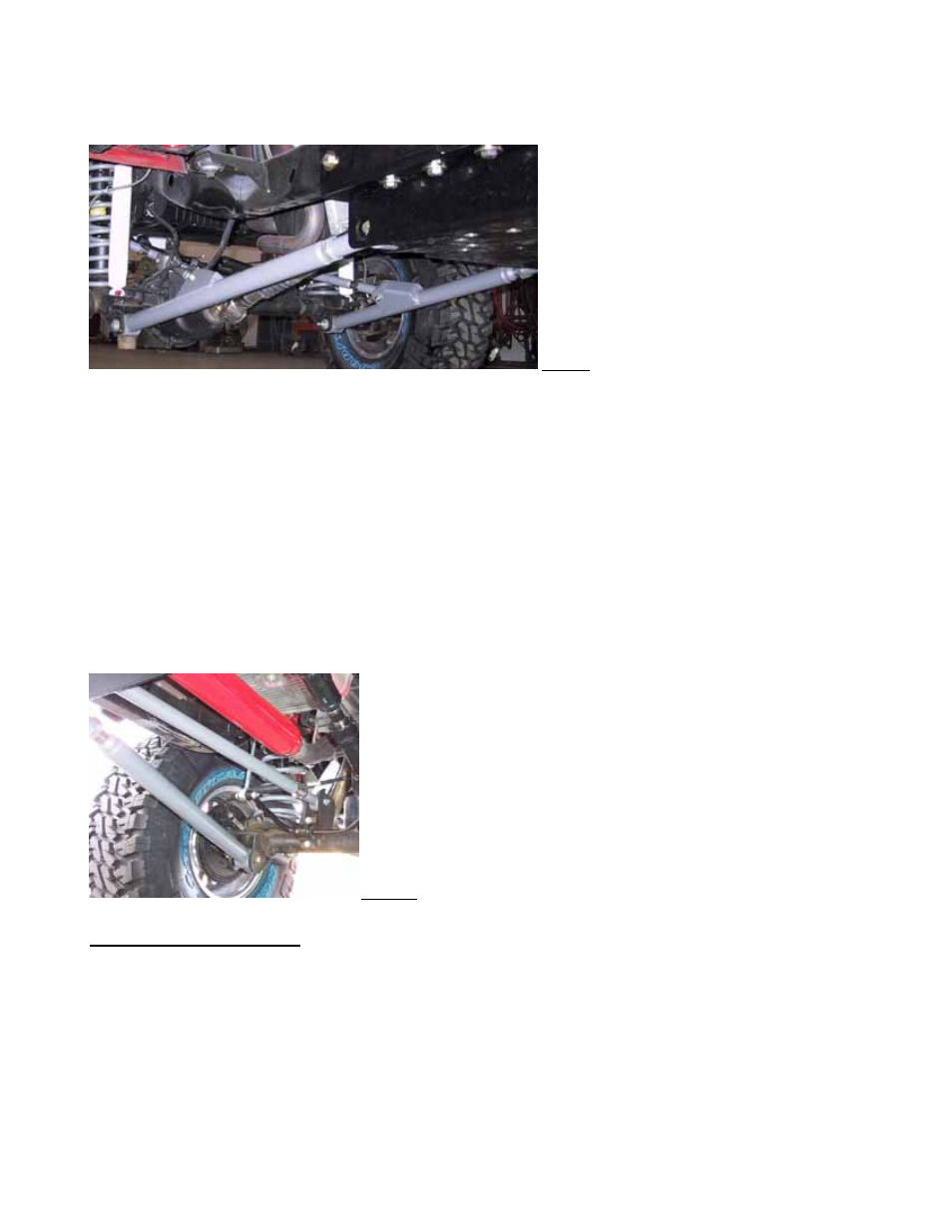
C.
Attach front lower control arms to axle with factory hardware, and attach upper arms to axle with supplied hardware – refer to
Photo 9. Checking distance from axle mount to front factory crossmember bolt should verify if axle is square, adjust if necessary.
Photo 9
D.
REAR - Adjust rear lower control arms’ length to an initial setting of about 32-5/8” from bolt center to bolt center. this
measurement will be 42.625”. Final arm lengths seem to vary from around 32-5/8” to 33.25” depending on lift, axle squareness
(see step F), tire size, and gas tank clearance. Install adjustable end of arm to rear crossmember lower mounts with supplied
hardware (zerk on bottom).
For LJ Unlimited: Adjust rear lower control arms’ length to an initial setting of about 42-5/8” from bolt center to bolt center.
Final arm lengths seem to vary from around 42-5/8” to 43-1/4” depending on lift, axle squareness (see step F), tire size, and gas
tank clearance. Install adjustable end of arm to rear crossmember lower mounts with supplied hardware (zerk on bottom).
E.
Adjust rear upper control arms’ length to an initial setting of about 33-5/8” (for 5.5” kits with CV shafts) from bolt center to bolt
center. For LJ Unlimited: This measurement needs to be 43-5/8”. It’s recommended that the 4.5” kits set this about 0.125” less
to drop the pinion a bit. The 3.5” kits may need the arms a bit shorter yet. Install the arms to rear crossmember upper mounts
with supplied hardware (zerk on top). The upper arms will be used to adjust final pinion angle.
F.
Attach rear lower control arms to axle with factory hardware. Checking the distance from axle mount to front factory
crossmember bolt should verify if axle is square, adjust if necessary. Attach upper arms to axle with supplied hardware (zerk on
top) – refer to Photo 10. Upper arms can be mounted either direction.
Photo 10
Step 4 – Bump stops and coils
A. REAR BUMP STOPS - Remove the rubber insert from the rear bump stop. Remove the bump stop cup. Place the spacer between
the bump stop cup and the tower using the supplied longer metric hardware. Reinstall stock rubber bump stop on 3.5” and 4.5”
kits, or install RE1395 extended bump stops on 5.5” kits - refer to Photo 11.
B. REAR COILS - Install rear coils.
RE7200G Page 5 of 8