Rubicon Express RE7200 SERIES User Manual
Page 2
TYPICAL TOOLS REQUIRED
1” hole saw(s) for steel, ½” drill motor & drill bits (including a high quality 5/8” bit), angle grinder,
Basic mechanical hand tools and T-55 Torx head bit along with standard Torx head wrench set,
Floor jack & jack stands (2 Pair), Pitman arm puller, welder
Plasma cutter, or reciprocating saw w/metal cutting blades, or cutting wheels for angle or die grinder (to remove control arm mounts)
INSTALLATION OVERVIEW
The installation process can be broken down into the following tasks:
1. Removal of factory lower control arm mounts on frame.
2. 3-piece frame crossmember.
3. Control
arms.
4. Bump stops and coils.
5. Track bars, pitman arm and sway bar links.
6. Brake lines and shocks.
7. Final detailing and adjustments.
Step 1 - Removal of factory lower control arm mounts on frame.
A. First, support vehicle by frame (preferably on a lift) and work on a stable level surface. Support axles with jack stands and
remove the following components; shocks, track bars, sway bar end links, coil springs, control arms, bump stops, brake hoses
from axle end (it may be helpful to pinch-off hoses with vise grips to minimize fluid loss until new SS hoses are installed in step
6), and exhaust system behind the catalytic converter. NOTE: Coil springs can be removed without compressors if enough
distance is generated between the axle and frame). If a lift is not being used, it may be easier to do this one side at a time on
one axle at a time. CAUTION: If using coil spring compressors use extreme care as they will be holding a lot of potential energy
and can release violently.
B. Cut off the (4) factory lower control arm mounts from the frame. Use extreme care as not to damage the frame, or cut into
existing brake, fuel, or electrical lines.
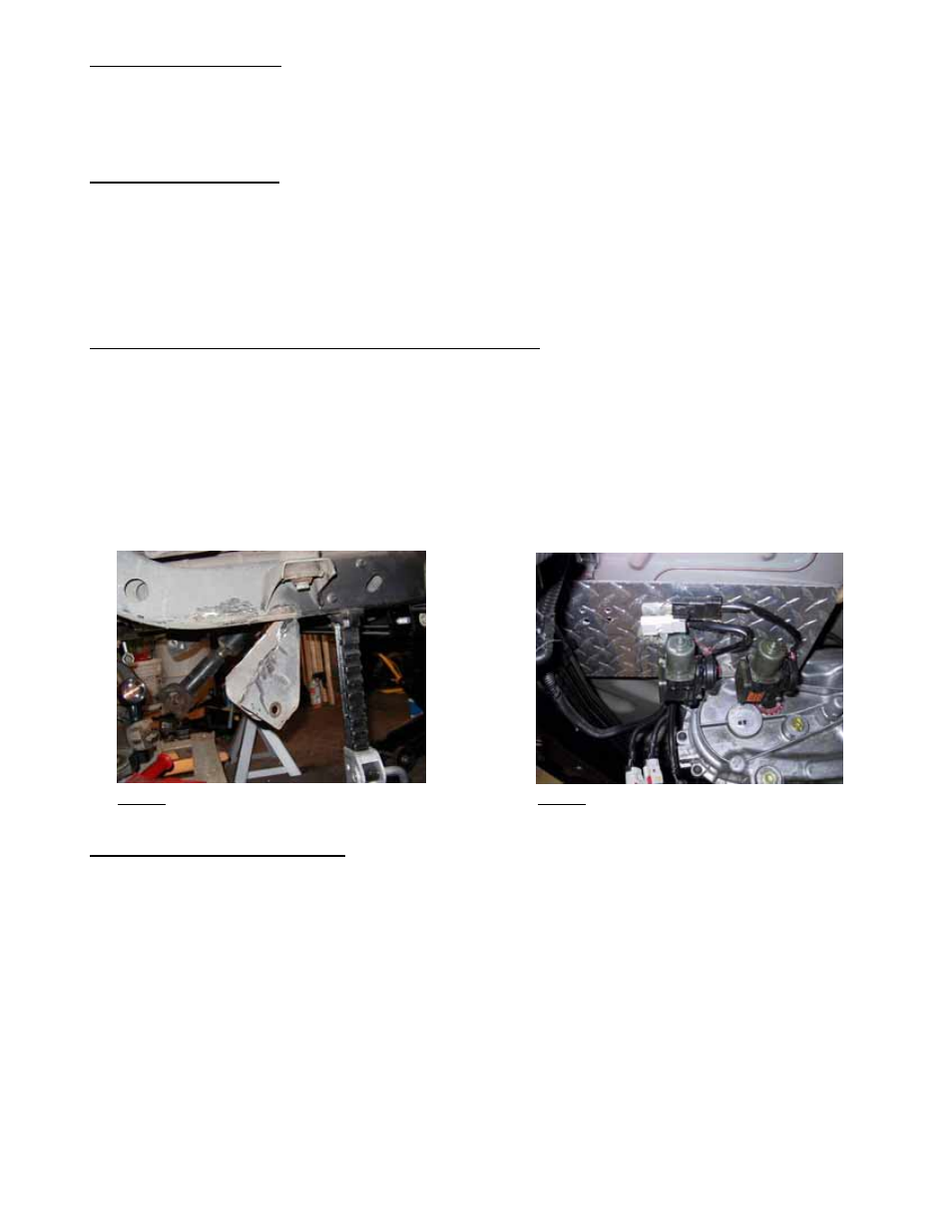
C. Grind rough areas smooth and repaint – refer to Photo 1 for typical bracket removal.
Photo 1
Photo 2
Step 2 - 3-piece frame crossmember
A. Support transmission and transfer case and remove stock crossmember. Note that the “Rubicon” model TJ’s will require that the
installer fabricate a bracket to relocate the compressor (refer to Photo 2 for an example).
B. Assemble the right and left control arm mounts to the center section using only a few supplied flat head bolts for fitment
purposes – refer to Photo 3 for orientation of parts. We will refer to this assembly from here on out as the “crossmember”.
RE7200G Page 2 of 8