Rubicon Express RE7363 User Manual
Page 8
RI73537363 Page 8 of 10
Photo # 20
Photo # 21
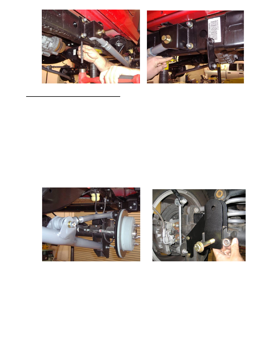
Step 5 – Rear arm and component installation
Rear arms
A.
Prepare the rear of the vehicle for control arm and component installation by removing the following items: shocks,
sway bar links, coil springs, track bar, brake line brackets at the frame, e-brake cables at the body and the driver’s side
upper and lower control arms.
B.
Pre set the lower rear long arms to 41 3/4” center to center and install the coupler end into the frame brackets with the
supplied 9/16” bolt, flat and lock washers. Attach the rubber bushing end into the lower control arm mount on the axle
housing using the factory hardware. Do not tighten the rubber bushing until the vehicle is on the ground to avoid
bushing preload.
C.
Set the upper arm to an initial setting of 17” center to center, install the coupler end at the mounting point on the lower
arm with the supplied ½” hardware and the other end at the upper mount on the axle using the factory hardware.
(photo 22)
D.
Repeat steps A – C on the passenger side.
E.
The upper arms may need to be to be readjusted after the installation is complete for proper pinion angle.
Photo # 22
Photo # 23
Rear track bar bracket and factory track bar
(photo 23)
NOTE: With the installation of the rear track bar bracket you may notice that at ride height, the axle is
not completely centered under the chassis; this is intentional. The reason for such offset at ride height
is to allow for proper tire to frame, and/or control arm clearance. Centering the axle under the chassis
at ride height may cause the tire to contact the frame and/or control arm which may result in tire
damage or failure!
A. With the axle properly supported remove the driver’s side rear lower control arm from the frame and axle.