Rubicon Express RE7363 User Manual
Page 3
RI73537363 Page 3 of 10
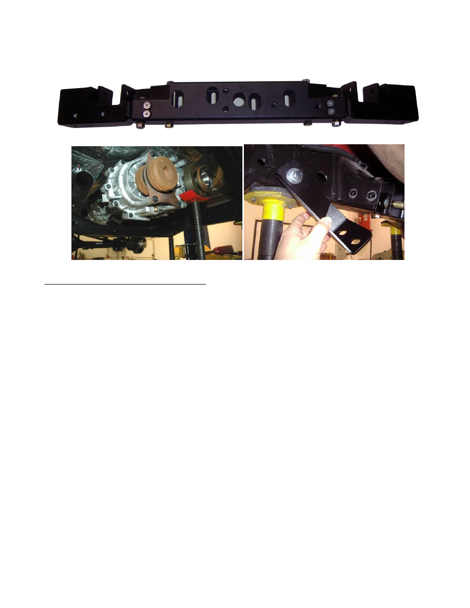
E. Install the new Rubicon Express cross member into the factory mounts with the control arm pockets facing forward. Reinstall the
4 factory cross member bolts thru the factory mounts and brace, tighten to 65 ft/lbs. Once tight, torque the forward cross
member brace bolt to 65 ft/lbs
F. Lower the transmission, install and tighten the transmission mount nuts. Re-check that all new or reused hardware has been
properly tightened.
Photo # 1
Photo #2
Photo#3
Step 3 – Front arm and component installation
NOTE: All of the dimensions listed for set up of the Rubicon Express control arms are base line
measurements for set up only. Due to differences in individual vehicle tolerances each vehicle
will need to be fine tuned for its particular lift height and tire size. Final adjustments should
be checked with the shocks installed and coil springs removed and the suspension cycled
from full compression to full droop including full articulation to the left and right side. Any
areas of contact should be addressed at this point by adjusting the control arms.
A. Prepare for the front end installation by removing the following items, Shocks, sway bar links, and track bar.
B. Remove the brake line attaching screw at the frame, unclip the abs wires from there attaching points for additional length, and
lower the breather hose clip on the shock tower approximately 6”.
Front arm Installation
A. Prepare the new Rubicon Express front lower long arms by pre setting the length to 36 3/4” center to center
B. Remove the passengers side factory upper and lower control arms.
NOTE:
It will be necessary to cut the upper control arm bolt off at the frame end to remove the passenger upper front arm.
This is due to the bolt being installed from the inside out prior to the exhaust installation from the factory. Alternatively
the head pipe assembly can be removed to pull the bolt out of the frame bracket. If choosing to unbolt the head pipe
be sure to disconnect all O2 sensors before removal. (photo 4)
NOTE:
To identify front left and right lower control arms lay each arm side by side on the ground as they would be installed in
the vehicle. At this point, both upper control arm pockets should be leaning toward each other or the center of the car.
The upper front arms are symmetrical and can be used on either the left or right side. (photo 6) Passenger side
shown.