Service instructions, General, Belt replacement – L.B. White 350 Premier User Manual
Page 15
Service Instructions
1. Close the fuel supply valve to the heater and
disconnect the electrical supply before servicing
unless necessary for your service procedure.
2. Clean the heater’s orifice with compressed air or a
soft, dry rag. Do not use files, drills, broaches, etc. to
clean the orifice hole. Doing so will enlarge the hole,
causing combustion or ignition problems. Replace
the orifice if it cannot be cleaned properly.
3. The high limit switches, HEAT/VENT switch, and
thermostat can be tested by disconnecting the leads
at the component, and jumpering the leads together.:
-- Reconnect the electrical supply and open fuel
supply valves.
-- If the heater lights, the component is defective
and must be replaced.
-- Do not leave the jumper on or operate the heater if
the part is defective. Replace the part immediately.
-- An alternate method for checking the components
is to perform a continuity check..
4. The air proving switch must not be jumpered. If
jumpered, the ignition control will not allow heater
operation. Test the air proving switch for continuity. If
defective, replace the switch
5. Open the respective case panel for access to burner
or fan related components.
6. For reassembly, reverse the respective service
procedure. Ensure gas connections are tightened
securely.
7 After servicing, start the heater to ensure proper
operation and check for gas leaks.
8. If sheave or fan keys are lost during ser vice,
replacements are made by using 3/16 square x 1 in.
bar stock. Otherwise, order Part #22955.
WARNING
B
Buurrnn H
Haazzaarrdd
■
Heater surfaces are hot for a period of time after the
heater has been shut down.
■
Allow the heater to cool before performing service,
maintenance, or cleaning.
■
Failure to follow this warning will result in burns
causing injury.
WARNING
FFiirree aanndd EExxpplloossiioonn H
Haazzaarrdd
■
Do not disassemble or attempt to repair any heater
components or gas train components.
■
All component parts must be replaced if defects are
found.
■
Failure to follow this warning will result in fire or
explosions, causing property damage, injury, or death.
GENERAL
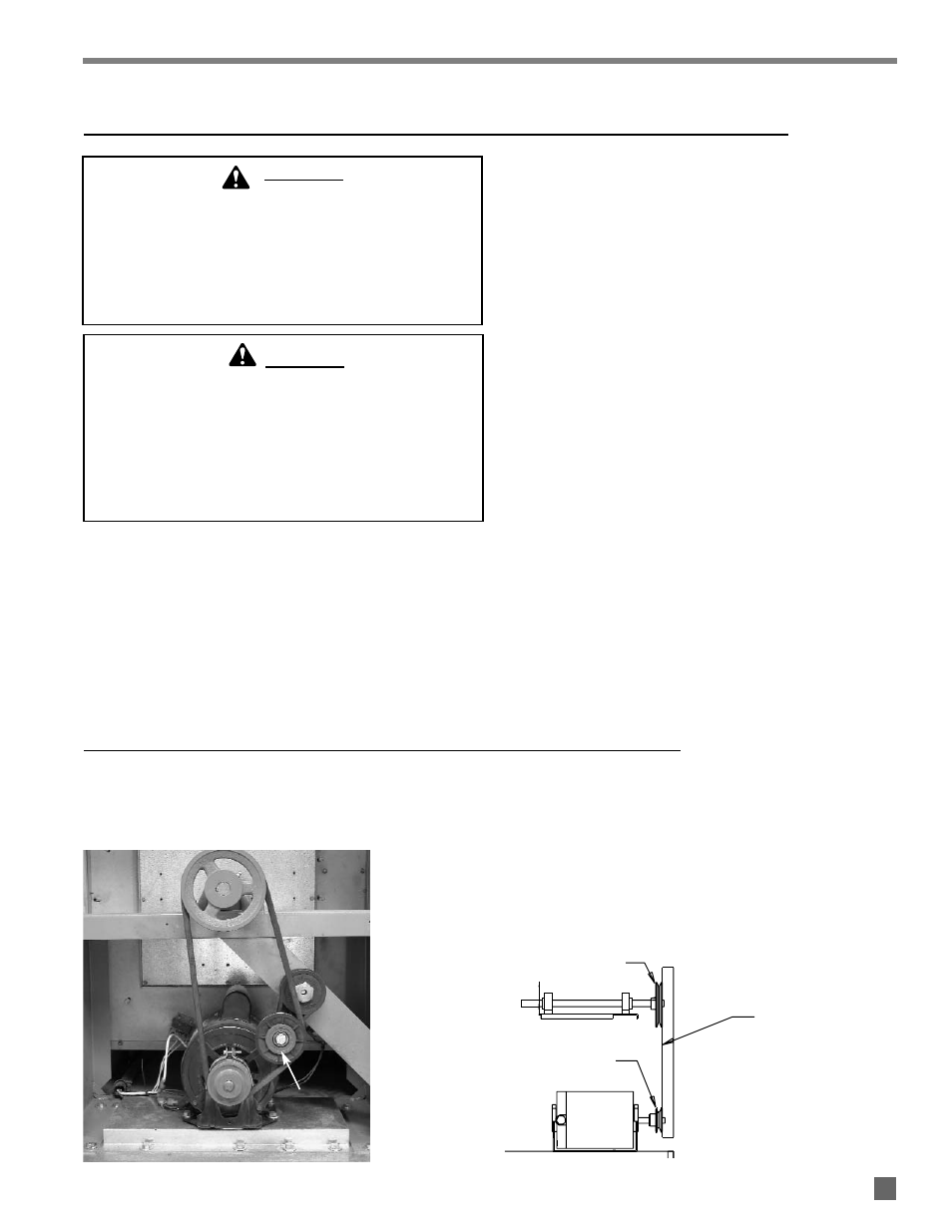
1. Push the belt tensioner clockwise for removal of the
belt from pulley. See Fig. 11.
FIG. 11
2
Check the fan and motor pulley grooves for dirt Clean
the pulleys if needed.
3. Install new belt. Using a straight edge, check motor
and fan pulley alignment. Contact must be made at
edges of both pulleys. See Fig. 12.
FIG. 12
BELT REPLACEMENT
TENSIONER
STRAIGHT
EDGE
FAN SHEAVE
MOTOR SHEAVE
FAN PULLEY
MOTOR PULLEY
14