Installing dust filter – L.B. White I-5 Infraconic User Manual
Page 10
10
The zone control panel is a remote mounted control system.
It allows non-electrical, modulating , thermostatically
controlled operation for a specific quantity of heaters within
a heating zone.
The panel will control the following quantity of heaters
depending on fuel type.
The zone control panel must be mounted to a flat, stable
wall inside the building. Use lag screws provided. For the
modulating zone panels, care must be taken to ensure that
the thermostatic control module is not exposed to outside
air temperatures. Exposure of the thermostatic control
module to outside air temperatures (Example: when
sidewall curtains are open) may cause the heater to provide
unwanted heat.
There are a number of optional configuration zone control
panels available. These include high and medium capacity,
modulating thermostatically controlled for stand alone, non-
electrical operation, as well as solenoid controlled for
incorporation into the building’s environmental control
system. Consult your local L. B. White dealer or distributor
or call the L. B. White Co. for recommendations on the best
configuration of zone panels for your specific application.
The zone control panel must have an adjustable high
pressure regulator installed upstream of the inlet of the
zone control panel. This regulator may be purchased from
the L. B. White Co. as an optional accessory. For L.P. gas,
the regulator must be capable of handling a maximum inlet
pressure of 10 psi, while supplying an outlet pressure of 5
psi nominal. This pressure is supplied to the zone control or
individual controlled heater. For natural gas, a regulator
must be installed to supply an outlet pressure of 5 psi
nominal.
ZONE CONTROL PANEL
COMPONENT FUNCTION AND INSTALLATION
Modulating System
Medium
High
Model and
Capacity
Capacity
Heat Output
Fuel
Panel
Panel
Quantity
Quantity
I5
L. P. Gas
46
(5,200 BTUH)
Natural Gas
26
132
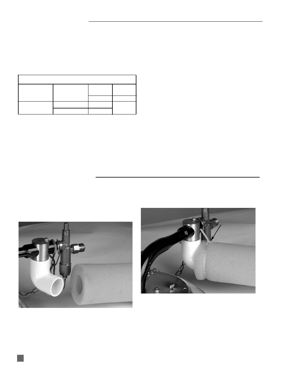
INSTALLING DUST FILTER
The filter is designed to provide additional dust filtration
capability and capacity for Infraconic heaters when
installed in severely dusty environments.
1. Position the filter sleeve onto the elbow. See Fig. 6a.
FIG.6a
2
Secure the sleeve to the elbow with the beaded cable
tie included with the filter. See Fig. 6b.
FIG.6b
3. Ensure that the filter does not sag or touch the
canopy of the heater.
ELBOW
FILTER
BEADED CABLE TIE