Interconnection – L.B. White FA-MCS-D User Manual
Page 7
■
Unlatch the control box cover, and open the control
panel.
■
Select locations on either the side or the bottom where
a wiring access holes may be drilled. Do not drill holes
at the top of the control box.
■
Install the appropriate sized water tight connectors.
■
Refer to the following for connection instructions. Refer
to t h e w h i te f l a g s o n t h e Smar tBox
™
l e a d s fo r
interconnections.
Connecting 120 VAC Power Supply to the SmartBox
™
.
Connect to hot, neutral, and ground leads as shown in
Fig.6.
FIG. 6
Connecting 120 VAC Power to the Heaters
Connect leads in SmartBox
™
to heating Zones 1 and 2.
See Fig.7.
FIG. 7
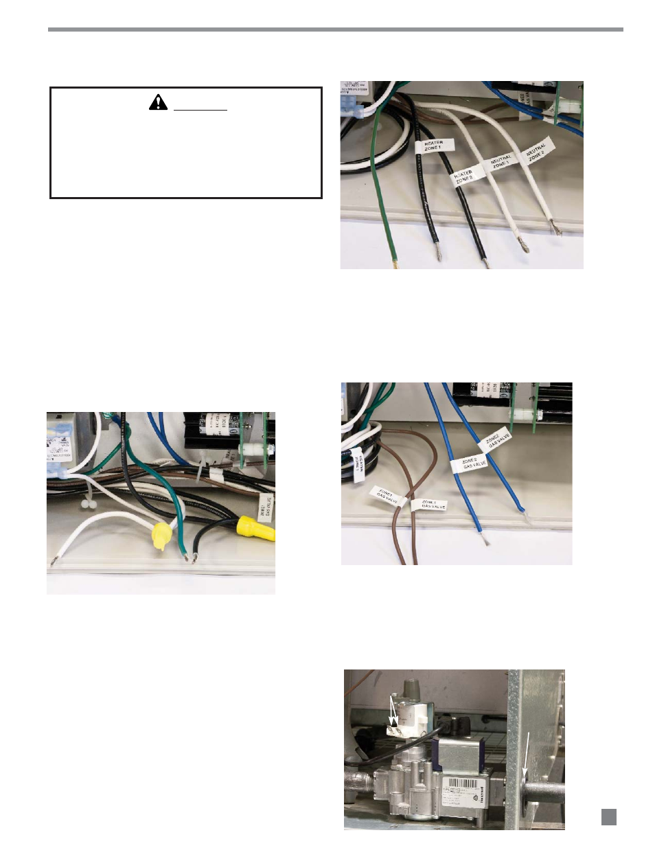
Wiring from the SmartBox
™
to the heater’s Smart Sense
™
variable rate gas control valve
a. Connect Smart Sense™ gas control valve wiring
for Zones 1 and 2 at SmartBox
™
leads as
shown in Fig.8.
FIG. 8
b. Route the wiring from these leads through the
gas inlet hole at the heater’s case. See Fig.9.
c. Attach 1/4 in. insulated female terminals to
these wires and connect to either terminal on
the valve. See Fig. 9.
FIG. 9
7
Interconnection
ROUTE WIRING
THROUGH HOLE
CONNECT WIRING TO TERMINALS
( NOT POLARITY SENSITIVE)
WARNING
Electrical Shock Hazard
■
Disconnect the electrical supply before installation of
the SmartBox
™
.
■
Failure to follow this warning may result in personal
injury or death.