Assembly, Assembly operation, Adjusting the mower blade – Steele Products SP-PM200M User Manual
Page 3: Warning
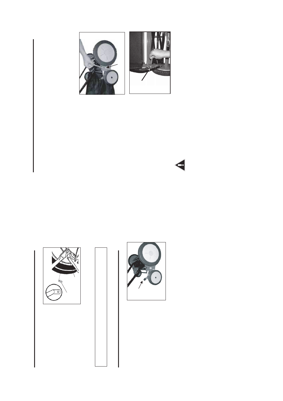
ASSEMBLY
OPERATION
A
T
TACHING THE HANDLE
T
O THE MOWER BASE
Front Mower
Fig.2
1
2
NOTE: It may be necessary to use the pliers in order to grip the
C-clips properly and to apply the required pressure.
CUTTING HEIGHT ADJUSTMENTS
Fig.3
1
1. After assembling the handle,
line up the holes at the lower
end of each handle arm with
the short posts that extend out
from the side plates of the
mower base.
2. Insert the posts into the holes
at the end of the handle arms,
and then snap the C-clips (1) onto the slotted posts (2) on both sides,
in order to prevent the handle from coming off.
1.The cutting height of the 20”
(50.8 cm) Reel Mower can be
adjusted from 1 3/4 to 2 3/4”
(4.5 to 7 cm) by moving the height
adjusment levers (1) to the
desired position. The height
adjusment levers are located
next to the smaller wheels.
2. In order to set the mower to its
lowest cutting position, pull the height adjustment levers (1) on both
sides to their highest positions.
3. In order to set the mower to its highest cutting position, move the
adjustment levers (1) on both sides to their lowest positions.
Note: The two height adjustors MUST be set to the same position (height).
4. The mower can be set to other cutting heights by moving the adjustors to
any position within their range.
- 5 -
ASSEMBLY
ADJUSTING THE MOWER BLADE
Fig.4
2
1
Fig.5
WARNING
Do not over-tighten the cutting bar, because doing so could damage the cutting bar and the blades.
NOTE: The blades were pre-adjusted prior to leaving the factory, but it is recommended that the adjustment be verified prior to the first use.
• Vibrations during shipping can cause misalignment, which often causes the blades to become too loose or too tight. This will result in a rough, uneven cut, or the mower will be hard to push.
1. Each end of the cutting bar can be adjusted separately. 2. The cutting bar blade, which is located under the reel, is able to pivot. The two adjustment nuts (2) located at the back of the mower move the cutting bar away from the blades when they are turned counter-clockwise, and closer to the blades when they are turned clockwise. 3. The upper locking nut (1) that is located between the front and rear radial wheels must be loosened before the cutting bar can be adjusted.
- 6 -