Fitting procedure general – ARB 3452020 User Manual
Page 8
Last Rev Date: 11-Sep-2006
Page 8 of 16
Fitting instructions# 3783239
Copyright © 2005 by ARB Corporation Limited. All rights reserved, this document must not be reproduced without the express authority of ARB Corporation Ltd
FITTING PROCEDURE GENERAL
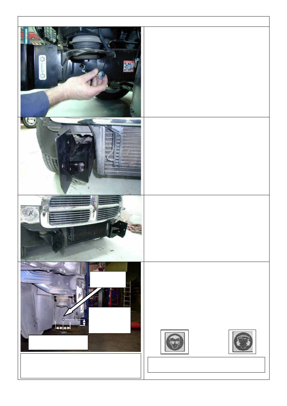
11. As shown, fit M10x100 bolt, sleeve, M10 x
3mm washer and flange nut and do up tight.
Note: Bolt head and washer outboard as
shown, nut to be on inside face of bracket.
2500 AND 3500 ONLY STEPS 12 - 18
12. Fit chassis brackets as shown.
13. Insert original U bolts, entering from inboard
face of chassis (you may have to tilt
intercooler to gain sufficient clearance to
allow U bolt to enter this side).
14. Set brackets so front edge is vertical then do
bolts up tight.
15. Replace the intercooler suspension blocks
and bolts if removed for U bolt removal.
16. Mark the position for the pinning hole
centrally between the body mount bracket
flanges as shown on the outboard face of the
chassis rails.
17. Drill through both sides of chassis and mount
bracket flange Dia 10.0mm. **CAUTION
18. Fit M10 x 100 pinning bolt, M10 x 3MM
washer and flange nut set and do up tight.
APPROX.
35mm FROM
UNDERSIDE
OF CHASSIS
LOCATE CENTRALLY
BETWEEN FLANGES
DRILL DIA
12.0mm
Warning: Drilling operations can result in flying
metal debris, safety glasses should be worn.
CAUTION: TAKE CARE NOT TO DRILL
THROUGH INTO THE RADIATOR ON
THE INSIDE OF CHASSIS.