Service (cont.) – Bunn G9-2T HD User Manual
Page 17
1 7
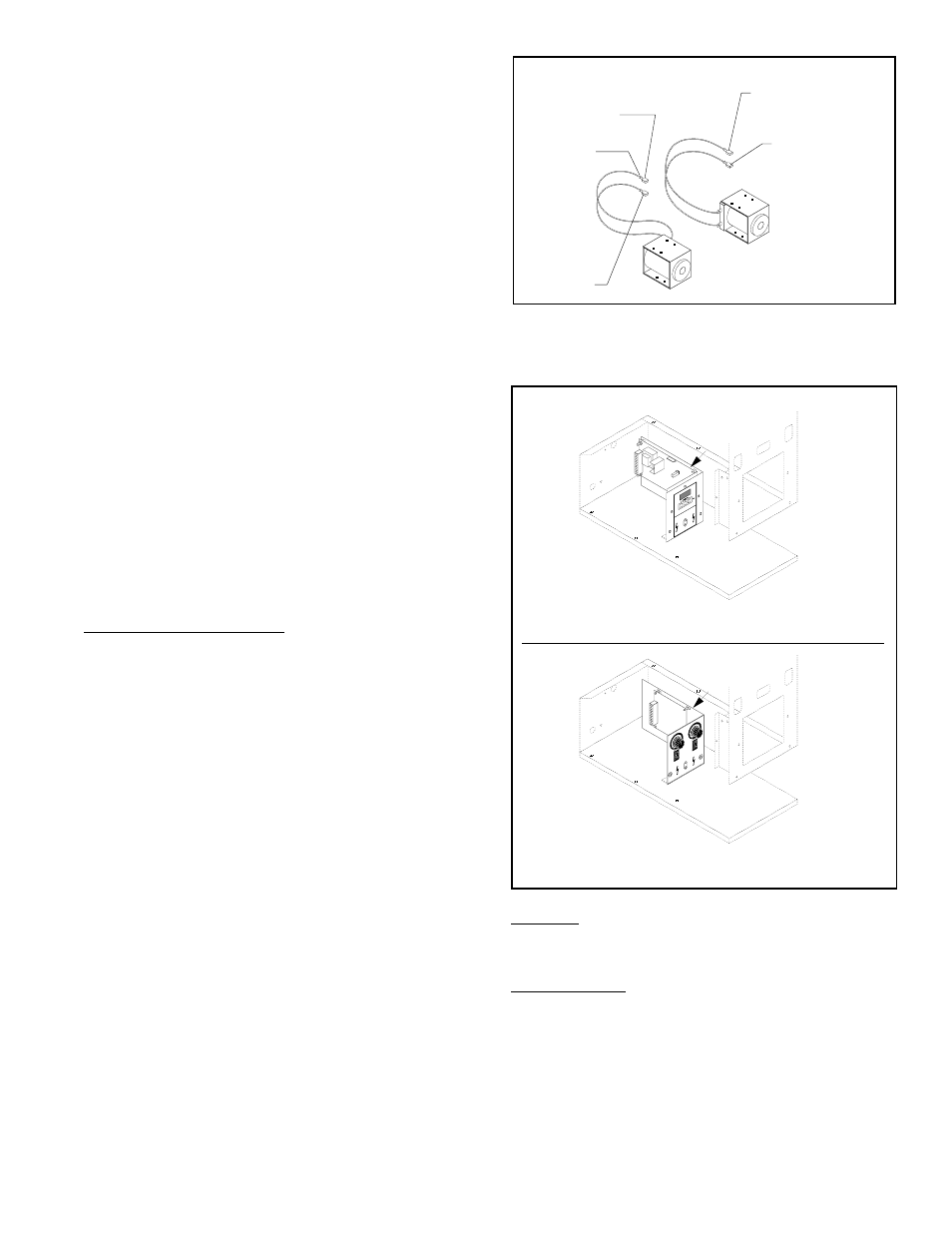
Timer
Location:
The timer is located in the grinder base.
Test Procedure:
1.
Unplug the grinder.
2.
Check the voltage across contacts 1 & 2 of the
larger connector on the timer board with a volt-
meter whenever the grinder is plugged-in. Plug-
in the grinder. The indication must be 120 volts
ac.
3.
Unplug the grinder.
SERVICE (cont.)
Solenoid(s) (cont.)
If continuity is present as described, reconnect
the white/brown wires to the grinder wiring harness,
and proceed to #6.
If continuity is not present as described, replace
the solenoid.
6.
Check the solenoid for coil action when the con-
trol switch is momentarily pressed to the
“START” (lower) position and released. Plug-in
the grinder. Listen carefully in the vicinity of the
solenoid for a “clicking” sound as the coil mag-
net attracts and after a period of time, repels the
plunger.
7.
Unplug the grinder.
If the sound is heard as described and the
plunger remains unable to move or move freely, refer
to the slide plate section.
If the sound is not heard as described, replace
the solenoid
Removal and Replacement:
1.
Remove the hopper assy from the grinder.
2.
Remove the four 8-32 slotted-head screws hold-
ing the solenoid coil to the solenoid panel.
3.
Feed the white/brown wires through the hole in
the solenoid mounting plate and loosely install
the new solenoid coil.
4.
Look through the collector on the bottom of the
assy and adjust the slide plate travel distance
when installing the solenoid coil.
5.
Push the solenoid plunger into the solenoid coil
with your hand while moving the coil forward
or backward in its mounting holes.
6.
Securely tighten the mounting screws when the
slide plate appears to have no metal showing in
the front or back of the hopper hole.
7.
Refer to the following illustration
when recon-
necting the wires.
Left
Right
WHI/ORN to
Timer P4-4
RED/BLK to
Right Solenoid
RED/BLK to
Timer P4-7
WHI/YEL to
Timer P4-5
RED/BLK to
Left Solenoid
P612
DISPENSE TIME (Seconds)
DISPLAY
Increase
Decrease
Re
ad
ou
t w
ill
be
di
sp
lay
ed
fo
r 5
m
inu
tes
.
Tim
er
ca
n o
nly
be
ad
jus
ted
wh
ile
re
ad
ou
t is
di
sp
lay
ed
.
+
WARNING
HA
ZA
RD
OU
S V
OL
TA
GE
UNPLUG GRINDER
BEFORE REMOVING
RI
GH
T
DIS
PE
NS
E T
IM
E
(SECO
NDS)
3.2
6
10
15
20
25
30
32
3.2
.4
.4
1
1
2
2
3
3
4
6
10
15
20
25
30
32
4
LE
FT
HI
GH
UNPLUG GRINDER
BEFORE REMOVING
WARNING
HA
ZA
RD
OU
S V
OL
TA
GE
HIG
H
LO
W
HI
GH
HIG
H
LO
W
LO
W
LO
W
O N
OFF
O N
OFF
P613
Digital Timer
Analog Timer