Ooking, P the, Elevision – Philips 32PT842H User Manual
Page 3: Av1 & av2 i
H
OOKING
U
P THE
T
ELEVISION
3
P
b
P
S-VIDEO
OUT
OUT
OUT
L
R
AUDIO
VIDEO
COMP VIDEO
Y
Pb
Pr
CVI
2
1
3
5
4
C
omponent Video inputs provide for the highest possible color
and picture resolution in the playback of digital signal source
material, such as with DVD players. The color difference signals
(Pb, Pr) and the luminance (Y) signal are connected and received
separately, which allows for improved color bandwidth informa-
tion (not possible when using composite video or S-Video connec-
tions).
1
Connect the Component (Y, Pb, Pr) Video OUT jacks
from the DVD player (or similar device) to the (Y, Pb, Pr)
in(put) jacks on the TV. When using the Component Video
Inputs, it is best not to connect a signal to the AV1 in Video
Jack.
2
Connect the red and white AUDIO CABLES to the
Audio (left and right) output jacks on the rear of the acces-
sory device to the Audio (L and R) AV1 in Input Jacks on
the TV.
3
Turn the TV and the DVD (or digital accessory device)
ON.
4
Press the AV button to scroll the available channels until
CVI appears in the upper left corner of the TV screen.
5
Insert a DVD disc into the DVD player and press the
PLAY
ᮣ
button on the DVD Player.
C
OMPONENT
V
IDEO
I
NPUTS
Refer to your DVD or digital accessory owner’s manual for def-
initions and connection details.
H
ELPFUL
H
INT
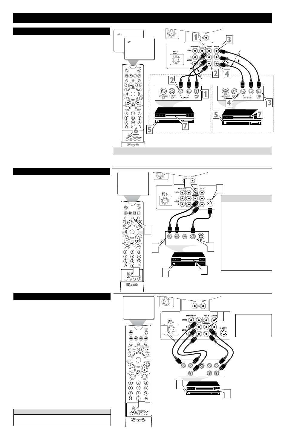
T
he TV’s audio/video input jacks are for direct picture and
sound connections between the TV and a VCR (or similar
device) that has audio/video output jacks. Both the AV1 and AV2
Input Jack connections are shown to the right, but either one can be
connected alone. Follow the easy steps below to connect your acces-
sory device to the AV1 and AV2 in Jacks located on the back of the
TV.
1
Connect the VIDEO (yellow) cable to the VIDEO AV1 in
(or AV2 in) jack on the back of the TV.
2
Connect the AUDIO (red and white) cables to the
AUDIO (left and right) AV1 in (or AV2 in) jacks on the
rear of the TV.
3
Connect the VIDEO (yellow) cable to the VIDEO OUT
jack on the back of the VCR (either one or two) or acces-
sory device being used.
4
Connect the AUDIO (red and white) cables to the
AUDIO (left and right) OUT jacks on the rear of the VCR
(either one or two) or accessory device being used.
5
Turn the VCR (either one or two) or accessory device
and the TV ON.
6
Press the AV button on the remote control to select the
AV1 channel for accessory device number one, or the AV2
channel for accessory device number two. AV1 or AV2 will
appear in the upper left corner on the TV screen depending
on the channel chosen.
7
With either of the VCRs (or accessory devices) ON and a
prerecorded tape (CD, DVD, etc.) inserted, press the
PLAY button to view the tape on the television.
AV1 & AV2 I
NPUTS
P
b
P
Note: The Audio/Video cables needed for this connection are not supplied with your TV. Please contact
your dealer or Philips at 800-531-0039 for information about purchasing the needed cables.
c C
HECK
I
T
O
UT
AUDIO IN
(RED/WHITE)
VCR TWO (or accessory device)
(EQUIPPED WITH VIDEO AND
AUDIO OUTPUT JACKS)
VIDEO IN
(YELLOW)
BACK OF VCR 1
BACK OF TV
AV1
Connection
AV2
Connection
VCR ONE (or accessory device)
(EQUIPPED WITH VIDEO AND
AUDIO OUTPUT JACKS)
AUDIO CABLES
(RED/WHITE)
COMPONENT
VIDEO CABLES
(Green, Blue, Red)
BACK OF TV
ACCESSORY DEVICE
EQUIPPED WITH COMPONENT
VIDEO OUTPUTS.
The CVI connection will be dom-
inate over the AV1 in Video
Input. When a Component Video
Device is connected as described,
it is best not to have a video sig-
nal connected to the AV1 in
Video Input jack.
BACK OF VCR 2
AUDIO IN
(RED/WHITE)
VIDEO IN (YELLOW)
T
he S(uper)-Video connection on the rear of the TV can provide
you with better picture detail and clarity for the playback of
accessory sources than the normal antenna picture connections.
NOTE: The accessory device must have an S-VIDEO OUT(put)
jack in order for you to complete the connection on this page.
1
Connect one end of the S-VIDEO CABLE to the S-
VIDEO jack on the back of the TV. Then connect one end
the AUDIO (red and white) CABLES to the AV2 in
AUDIO L and R(left and right) jacks on the rear of the TV.
2
Connect other end of the S-VIDEO CABLE to the S-
VIDEO OUT jack on the back of the VCR. Then connect
the other ends of the AUDIO (red and white) CABLES to
the AUDIO (left and right) OUT jacks on the rear of the
VCR.
3
Turn the VCR and the TV ON.
4
Press the AV button on the remote to scroll the channels
until SVHS appears in the upper left corner of the TV
screen.
5
Slide the TV/VCR/ACC switch to the VCR position.
6
Now your ready to place a prerecorded video tape in the
VCR and press the PLAY
ᮣ
button.
S-V
IDEO
I
NPUTS
P
b
P
AUDIO OUT
L R
S-VIDEO
OUT
ANT/CABLE
OUT
VIDEO
OUT
SVHS
1
2
1
2
3
6
4
5
The S-VIDEO and VIDEO AV2
in(puts) are in parallel. The S-
VIDEO input is dominant when
in use. If separate video signals
are connected to the S-VIDEO
and VIDEO AV2 in(puts), the
signal from the VIDEO AV2
in(put) will not be usable.
Note: The S-Video and Audio
cables needed for this connection
are not supplied with your TV.
Please contact your dealer or
Philips at 800-531-0039 for
information about purchasing the
needed cables.
H
ELPFUL
H
INT
AUDIO CABLE
(RED/WHITE)
VCR
(EQUIPPED WITH
S-VIDEO JACKS)
S-VIDEO
CABLE
BACK OF VCR