B&B Electronics Parallel Printer Card PIOC User Manual
Page 7
6
Documentation Number PIOC2595 Manual
B&B Electronics -- PO Box 1040 -- Ottawa, IL 61350
PH (815) 433-5100 -- FAX (815) 433-5105
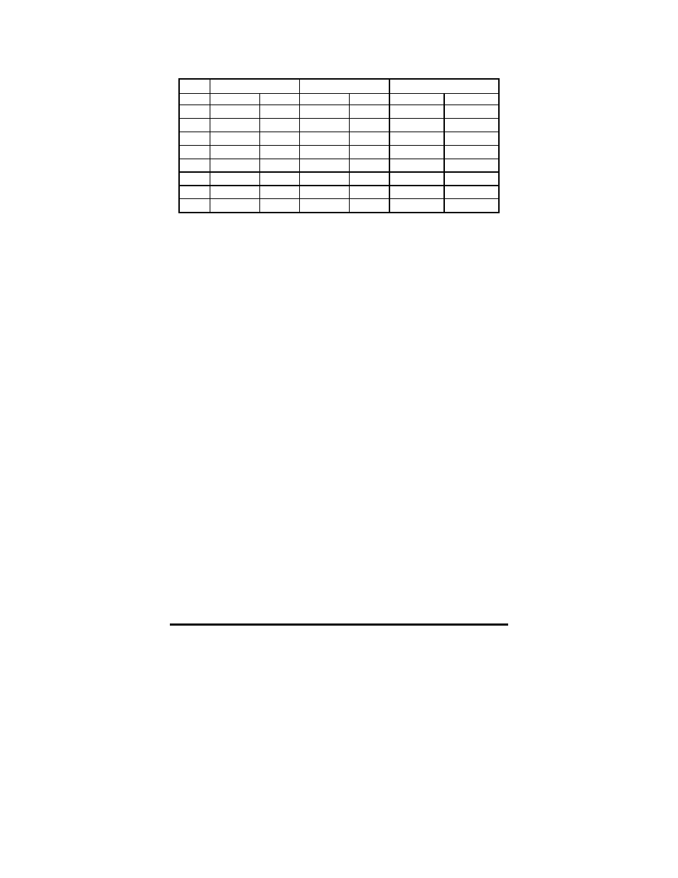
Table 5 - Register Functions and Pinouts
NOTE 1: An "X" means no connection to any DB-25 pins.
NOTE 2: Bit 4 of the Control Register (37AH) as an output is used
to control IRQ7. When this bit is high, IRQ7 is enabled and when
this bit is low, IRQ7 is disabled. As an input this reads the status of
the Interrupt Enable.
NOTE 3: This bit is used to control the direction of the Base
Register (378H). Outputting a “1” to this bit defines the lines as
inputs. Outputting a “0”, which is default, to this bit defines the lines
as outputs.
BIT
Base (378H)
Status (379H)
Control (37AH)
OUTPUT INPUT OUTPUT INPUT OUTPUT
INPUT
0 2 2 X X 1
1
1 3 3 X X 14 14
2 4 4 X X 16 16
3 5 5 X 15 17 17
4 6 6 X 13
See Note 2
See Note2
5 7 7 X 12
See Note 3
See Note 3
6 8 8 X 10 X
X
7 9 9 X 11 X
X