3changing over the door hinges, Putting into operation, 3 changing over the door hinges – Liebherr GN 2723 Comfort NoFrost User Manual
Page 6
u
Align the appliance so that it
stands firmly and on a level by
applying the accompanying
spanner to the adjustable-
height feet (A) and using a
spirit level.
Note
u
Clean the appliance (see 6.2) .
If the appliance is installed in a very damp environment,
condensate may form on the outside of the appliance.
u
Always see to good ventilation at the installation site.
4.3 Changing over the door hinges
You can change over the door hinges if necessary.
Ensure that the following tools are to hand:
q
Torx 25
q
Torx 15
q
Open-ended spanner size 6
q
Screwdriver
q
Open-ended spanner included in supply package
q
Second person for fitting work, if needed
CAUTION
Risk of injury if the door tips!
u
Take good hold of the door.
u
Set down the door carefully.
u
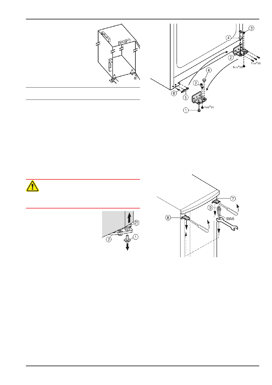
Unscrew the securing screw on
the bottom right turn hinge.
u
Open the door.
u
Hold the door on the handle side
and at the bottom and lift it.
w
The bearing pin
Fig. 4 (21)
should
come out of the turn hinge
Fig. 5 (2)
.
u
If the bearing pin
Fig. 4 (21)
does
not come out, press the pin out
from underneath.
Fig. 4
u
Swing door out at the bottom and remove it.
Fig. 5
u
Unscrew the turn hinge
Fig. 5 (2)
.
u
Unscrew the bearing element,
Fig. 5 (3)
transfer it to the
opposite location hole of the turn hinge and screw it firmly
into place.
u
Take the stopper
Fig. 5 (4)
out of the turn hinge and transfer
it to the receiving hole on the opposite side of the turn hinge.
u
Carefully lift off the cover
Fig. 5 (5)
on the handle side.
u
Undo the screw
Fig. 5 (6)
and transfer it to the opposite side.
u
Put the cover
Fig. 5 (5)
back on.
u
Screw the turn hinge
Fig. 5 (2)
firmly into place on the new
hinge side (with 4 Nm), possibly using a power screwdriver.
Fig. 6
u
At the top, use a screwdriver to unclip cover
Fig. 6 (7)
and
cover
Fig. 6 (8)
at the front, and remove by pulling out and
down.
u
Unscrew the bearing pin
Fig. 6 (9)
and screw it firmly into
place on the opposite side (with 4 Nm).
u
Refit the cover
Fig. 6 (7)
on the side of the bearing pin: insert
at the back, snap in at the front.
u
Fit the cover
Fig. 6 (8)
on the opposite side: insert at the
back, snap in at the front.
Putting into operation
6
* Depending on model and options