BKI COB-E User Manual
Page 11
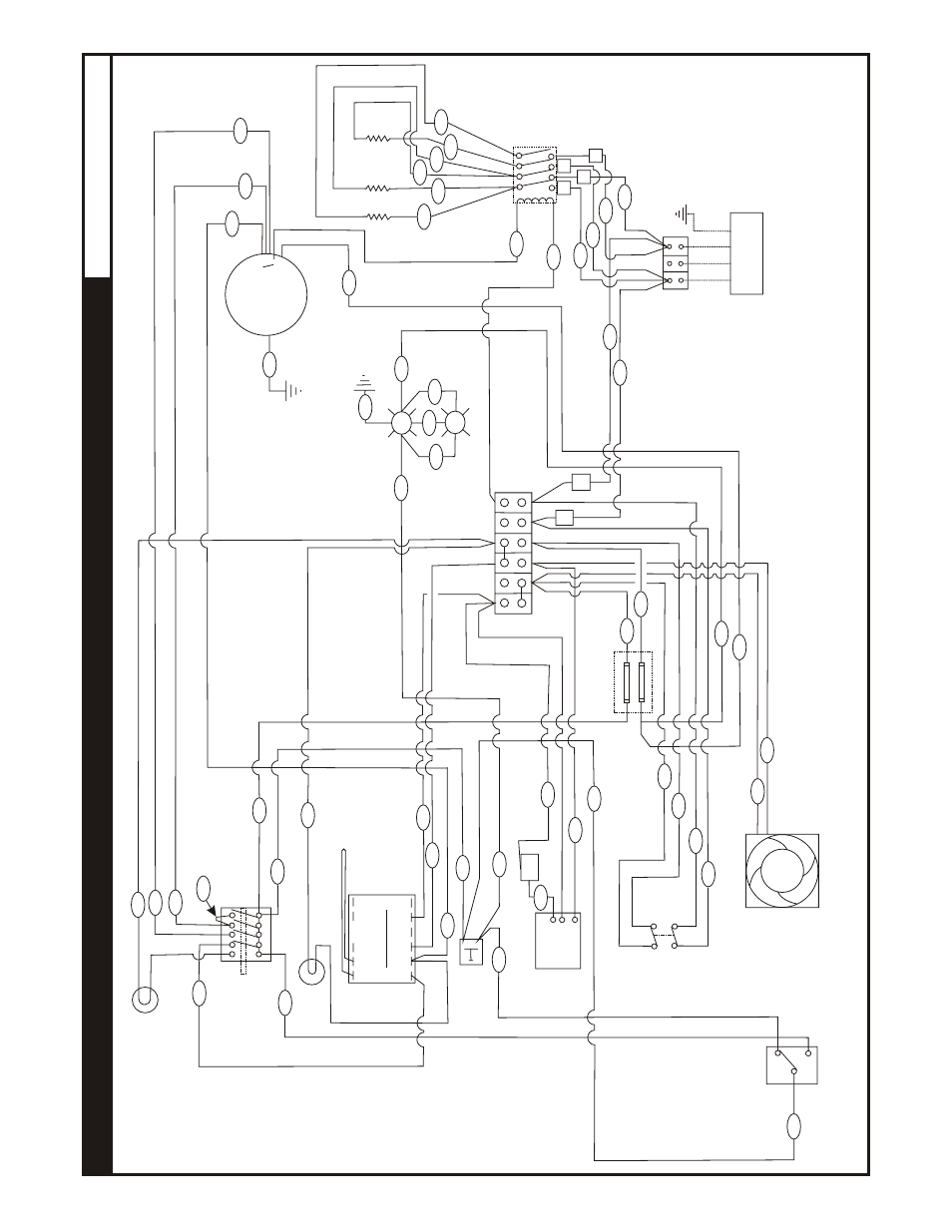
COB-E
&
COM-E
208,
or
240V
AC,
1
Phase
(Dial
Control)
E.
WIRING
DIAGRAMS
18
2
1
27
Green
Power
Light
23
10
30
Amber
Pilot
Light
19
24
RTD
Probe
T4
T5
T2
T1
T3
T6
T7
T8
T9
T10
T1
1
Probe
T-Stat
Relay
Thermostat
26
25
4
23
Light
Push
Button
Switch
28
9
Buzzer
50
22
21
29
4
1
Timer
29
NC
C
NO
Doors
Close
To
Activate
Switch
Power
16
17
14
15
43
44
3
6
Cooling
Fan
Fuse
Box
45
46
L1
L2
13
12
L1
L2
L3
Ground
Stud
Single
Phase
208
or
240V
38
39
41
42
5
11
A1
A2
L1
L1
4
Pole
40
Amp
Contactor
L2
L2
32
37
33
36
34
35
3
Com
Front
Element
T3
to
T2
T1
to
T2
T1
to
T4
Lights
48
9
6
8
47
7
4
1
2
Motor
Centrifugal
Switch
2
Speed
1725/850
49
11