Chute and tube installation – Briggs & Stratton 1695284 User Manual
Page 10
8
Chute and Tube Installation
C
A
B
E
F
D
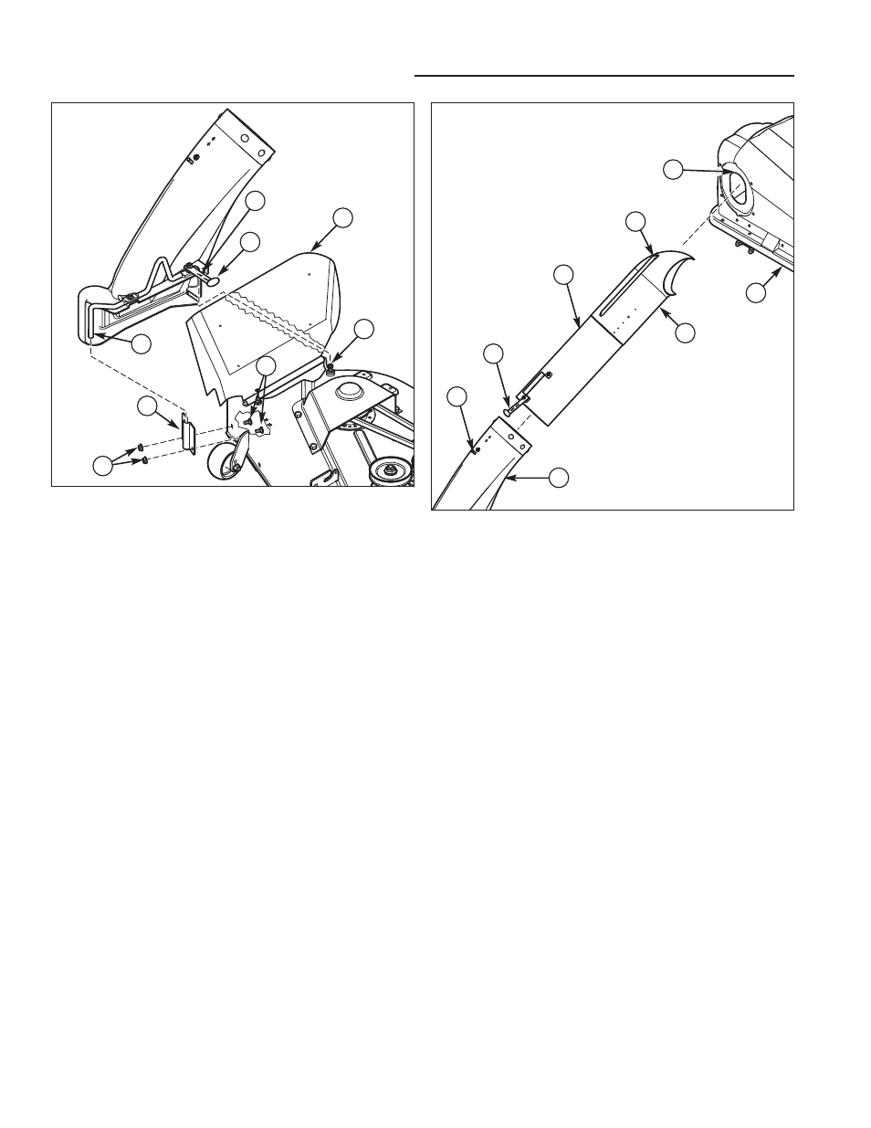
Figure 10. Connecting Tube Assembly to Lower
Chute and Cover
A. Upper Tube
B. Cover
C. Ridge, Upper Tube
D. Ridge Cutout
E. Lower Chute
F. Strap, Rubber
G. Pin
H. Tube Assembly
CONNECTING TUBE ASSEMBLY TO CHUTE AND COVER
1. Slide the upper tube (A, Figure 10) into cover (B)
aligning ridge (C) with cutout (D) as shown.
2. Slide tube assembly(H) over lower chute (E). Secure
tube assembly (H) to lower chute (E) using strap (F)
and pin (G).
G
H
Figure 9. Install Chute
A. Mounting Plate
B. Locknuts, 5/16-18
C. Carriage Bolt, 5/16-18 x 5/8
D. Chute Rod
E. Rubber Strap
F. Discharge Deflector
G. Locknut
H. Mounting Hole
A
B
C
D
E
F
G
H
Chute Installation
1. Install mounting plate (A, Figure 9) to mower deck as
shown. Secure with 5/16-18 x 5/8 carriage bolts (C)
and 5/16-18 locknuts (B).
2. Lift discharge deflector (F).
3. Insert lower chute rod (D) into mounting plate (A).
4. Pull rubber strap (E) below discharge deflector, and
secure by placing hole (H) over locknut (G).