Eurorack ub1622fx, Ub1832fx, Ub2222fx – Behringer UB2222FX-PRO User Manual
Page 13: Ub2442fx
13
EURORACK UB1622FX
-PRO
/UB1832FX
-PRO
/UB2222FX
-PRO
/UB2442FX
-PRO
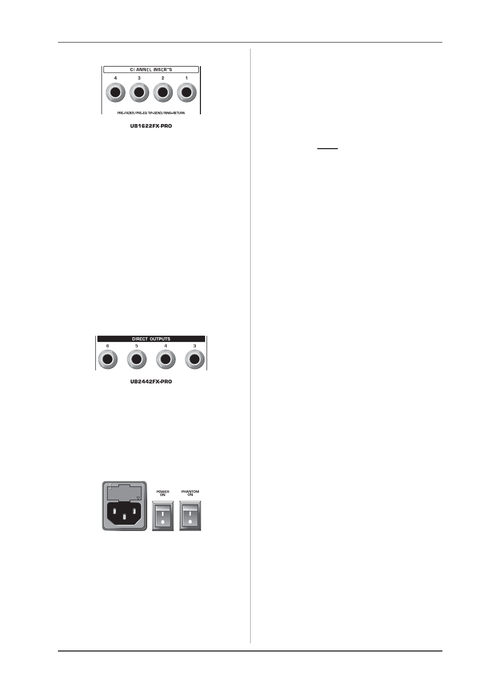
5.3 Inserts
Fig. 5.3: Insert points
+
On the UB2442FX-PRO the channel insert points are
located on the control panel between the line input
and the gain control.
Insert points are very useful to process channel signals with
dynamic processors or equalizers. Unlike reverb or other effects
devices, whose signals are usually added to the dry signal,
dynamic processors are most effective on the complete signal.
In this case, aux send paths are a less-than-perfect solution. It is
better to interrupt the signal path and insert a dynamic processor
and/or equalizer. After processing, the signal is routed back to
the console at precisely the same point it left. However, the
channel signal path is interrupted only if a plug is inserted into the
corresponding jack (stereo phone plug: tip = signal output; ring =
return input). All mono input channels are equipped with inserts.
They are pre-fader, pre-EQ and pre-aux send. Inserts can also
be used as pre-EQ direct outputs, without interrupting the signal
path. To this end, you will need a cable fitted with mono phone
plugs on the tape machine or effect device end, and a bridged
stereo phone plug on the console side (tip and ring connected).
5.4 Direct outputs (UB2442FX-PRO only)
Fig. 5.4: Direct outputs
DIRECT OUTPUTS
The direct outputs of the UB2442FX-PRO (1 each per mono
input channel) are ideal for recording if several tracks are to be
recorded simultaneously. These unbalanced phone jacks are
post-EQ, post-mute and post-fader.
5.5 Voltage supply, phantom power supply
and fuse
Fig. 5.5: Voltage supply and fuse
FUSEHOLDER
The console is connected to the mains via the supplied cable;
this comes complete with IEC mains connector. It meets the
required safety standards. Blown fuses must only be replaced
by fuses of the same type and rating.
IEC MAINS RECEPTACLE
The mains connection is via a cable with IEC mains connector.
An appropriate mains cable is supplied with the equipment.
POWER switch
Use the POWER switch to turn on the mixing console.
PHANTOM switch
The PHANTOM switch activates the phantom power
(necessary to operate condenser microphones) on the XLR
sockets of the mono channels. The red +48 V LED illuminates
when phantom power is on. As a rule, dynamic microphones
can still be used with phantom power, provided that they are
wired in a balanced configuration. In case of doubt, contact the
microphone manufacturer!
+
While phantom power is switched on, do not
connect or disconnect any microphones on the
mixer (or the stagebox/wallbox). Connect the
microphones before you switch on phantom power.
In addition, the monitor/PA speakers should be
muted before activating the phantom power supply.
After switching on, wait approx. one minute before
setting the input gain so that the system has time
to stabilize.
+
Caution! Please also note the information given in
chapter 6.2.1 Audio connections.
SERIAL NUMBER
Please note the important information on the serial number
given in chapter 1.3.3.
5. REAR PANEL CONNECTORS