Switches, 1 display switch, 2 dip switches – BIXOLON BCD-1100 User Manual
Page 11: 1 display switch 6-2 dip switches, Rev. 1.00
Rev. 1.00
- 11 -
BCD-1100
6. Switches
6-1 Display Switch
6-1-1 Feature : A Display Switch is located on the bottom of the display panel.
6-1-2 Function : Turns the power supply on/off.
6-2 DIP switches
6-2-1 Feature : Two DIP switches are located on the back of the display panel.
You can remove the DIP switch cover by pushing the hook.
6-2-2 Function: DIP switch settings can be read only when the power is on.
Therefore, any changes to the settings when the power is on do not take
effect
.
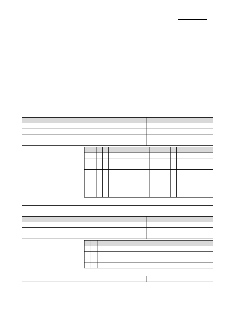
6-2-3 DIP S/W #1 Function (RS-232 Serial Input Setting)
No.
Function
Switch OFF
Switch ON
1
Default Setting
DIP Switch Values
EEP-ROM Data Leading
2 Reserved
-
-
3
Display Viewing Side
Customer Side
Operator Side
4
Self-test Execution
Does not execute
Executes
5~8 Emulation
5 6 7 8
Emulation
5 6 7 8
Emulation
0 0 0 0
Samsung VFD
1 0 0 0 NCR Real POS
0 0 0 1 Epson ESC/POS 1 0 0 1
PD6000
0 0 1 0
ADM787/788 1 0 1 0
ICD2002
0 0 1 1
DSP800
1 0 1 1
Reserved
0 1 0 0
AEDEX
1 1 0 0
Reserved
0 1 0 1
UTC Standard 1 1 0 1
Reserved
0 1 1 0
UTC Enhance 1 1 1 0
Reserved
0 1 1 1
CD5220
1 1 1 1
Reserved
(“0” : S/W OFF, “1” : S/W ON)
6-2-4 DIP S/W #2 Function (Command Emulation Mode and Self Test Setting)
No.
Function
Switch OFF
Switch ON
1
Data Length
8 bits
7 bits
2
Parity using
Non parity
Parity
3 Parity
Selection
Odd
Even
4~6 Transmit
Speed
4 5 6
Transmit Speed 4 5 6
Transmit Speed
0 0 0
9,600 bps
1 0 0
115,200 bps
0 0 0
4,800 bps
1 0 1
57,600 bps
0 1 1
2,400 bps
1 1 0
38,400 bps
0 1 0
1,200 bps
1 1 1
19,200 bps
(“0” : S/W OFF, “1” : S/W ON)
7~8 Reserved
-
-