Warning, Main – Bryant Single Packaged And Gas Furnace System 577D User Manual
Page 7
7
90
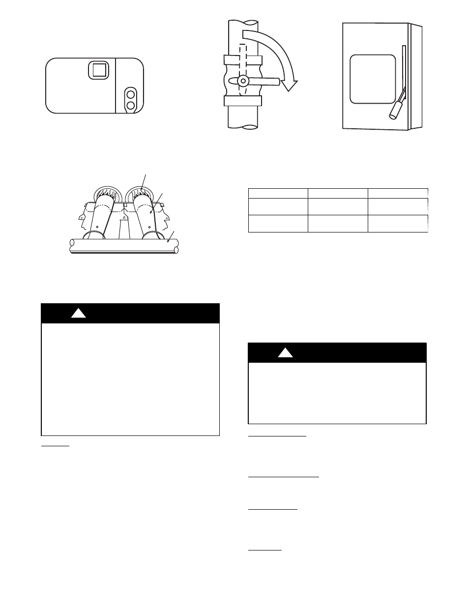
STEP 1
STEP 2
CLO
SE
STEP 3
OFF
ON
MAIN
A07797
Fig. 7 -- To Shut--off Unit Electric Cooling
MANIFOLD
BURNER
BURNER FLAME
C99021
Fig. 8 -- Monoport Burner
Maintenance and Care for the Equipment Owner
Before proceeding with those things you might want to maintain
yourself, please carefully consider the following:
FIRE, EXPLOSION, ELECTRICAL SHOCK AND
CUT HAZARD
Failure to follow this warning could result in personal injury,
death or property damage.
1. TURN OFF ELECTRICAL POWER TO YOUR UNIT
BEFORE
SERVICING
OR
PERFORMING
MAINTENANCE.
2. When removing access panels or performing maintenance
functions inside your unit, be aware of sharp sheet metal
parts and screws. Although special care is taken to reduce
sharp edges to a minimum, be extremely careful when
handling parts or reaching into the unit.
!
WARNING
Air Filters
The air filter(s) should be checked every 3 or 4 weeks and changed
or cleaned whenever it becomes dirty. Dirty filters produce exces-
sive stress on the blower motor and can cause the motor to overheat
and shut down.
This unit must have air filters in place before it can be operated.
These filters can be located in one of at least two places. In many ap-
plications, the installer will provide return air filter grilles mounted
on the wall or ceiling of the conditioned structure. In the instance of
filter grilles, the filters can simply be removed from the grille and re-
placed.
The other typical application is an accessory filter rack installed in-
side the unit itself. The following information is given to assist in
changing filters used in these internal filter racks.
Table 1 indicates the correct filter size for your unit. Refer to Fig. 2
to access filters installed in the accessory filter rack.
Table 1—Air Filters Located Inside Unit
(For Replacement Purposes)
Unit Size
Quantity
Filter Size in. (mm)
A24---A30
2
12x20x1
(305x508x25)
A36---A60
3
12x24x1
(305x610x25)
To replace or inspect filters in accessory filter rack (See Fig. 2):
1. Remove the filter access panel using a 5/16--in. nut driver.
2. Remove the filter(s) by pulling it out of the unit. If the filter(s)
is dirty, clean or replace with a new one.
When installing the new filter(s), note the direction of the airflow
arrows on the filter frame.
If you have difficulty locating your air filter(s) or have questions
concerning proper filter maintenance, contact your dealer for in-
structions. When replacing filters, always use the same size and type
of filter that was supplied originally by the installer.
FIRE AND UNIT OPERATION HAZARD
Failure to follow this warning could result in personal injury,
death or property damage.
Never operate your unit without filters in place. An
accumulation of dust and lint on internal parts of your unit can
cause loss of efficiency.
!
WARNING
Fans and Fan Motors
Periodically check the condition of fan wheels and housings and
fan--motor shaft bearings. Contact your dealer for the required
annual maintenance.
Indoor and Outdoor Coils
Cleaning of the coils should only be done by qualified service per-
sonnel. Contact your dealer for the required annual maintenance.
Condensate Drain
The drain pan and condensate drain line should be checked and
cleaned at the same time the cooling coils are checked by your deal-
er.
Compressor
All compressors are factory shipped with a normal charge of the cor-
rect type of refrigeration grade oil. A compressor should rarely re-
quire additional oil.