Installation, Specifications – Pioneer PRS-D400 User Manual
Page 9
9
EN
G
L
IS
H
Installation
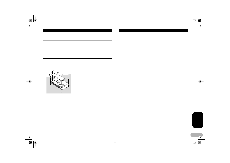
Example of installation on the floor mat or on the
chassis
1. Place the amplifier where it is to be installed. Insert the supplied tapping screws
(4 x 18 mm) into the screw holes. Push on the screws with a screwdriver so they
make marks where the installation holes are to be located.
2. Drill 2.5 mm diameter holes at the point marked, and install the amplifier, either
on the carpet or directly to the chassis.
Replacing the terminal cover
1. Align the unit and terminal cover, and insert the screw.
2. Tighten the screw with a 4 mm hexagonal wrench.
Drill a 2.5 mm diameter hole
Floor mat or chassis
Screw
Tapping screws (4
x 18 mm)
Terminal Cover
Specifications
Power source .......................................................................... 14.4 V DC (10.8 V to 15.1 V allowable)
Grounding system .......................................................................................................... Negative type
Current consumption ...................................................................... 27.7 A (at continuous power, 4 Ω)
Average current drawn* ......................................................................... 10.4 A (4 Ω for four channels)
20.2 A (4 Ω for two channels)
20.2 A (2 Ω for four channels)
Fuse ......................................................................................................................................... 30 A
x 2
Dimensions ......................................................................................... 304 (W)
x 56 (H) x 202 (D) mm
Weight ....................................................................................... 3.0 kg (Leads for wiring not included)
Maximum power output .................................................................. 150 W
x 4 (4 Ω) / 600 W x 2 (4 Ω)
Continuous power output ................................. 75 W
x 4 (at 14.4 V, 4 Ω, 20 Hz to 20 kHz 1.0% THD)
300 W
x 2 (at 14.4 V, 4 Ω, 1 kHz 1.0% THD)
150 W
x 4 (at 14.4 V, 2 Ω, 1 kHz 1.0% THD)
Load impedance .......................................................................................... 4 Ω (2 Ω to 8 Ω allowable)
(Bridge connection: 4 Ω to 8 Ω allowable)
Frequency response ........................................................................... 10 Hz to 40 kHz (+0 dB, –3 dB)
Signal-to-noise ratio ........................................................................................ 100 dB (IEC-A network)
Distortion .......................................................................................................... 0.005 % (10 W, 1 kHz)
Separation ...................................................................................................................... 70 dB (1 kHz)
Low pass filter ................................................................................ Cut off frequency: 40 Hz to 120 Hz
Cut off slope: –12 dB/oct
High pass filter ............................................................................... Cut off frequency: 40 Hz to 120 Hz
Cut off slope: –12 dB/oct
Gain control ....................................................................................................... RCA: 400 mV to 6.5 V
Speaker: 1.6 V to 26 V
Maximum input level / impedance .......................................................................... RCA: 6.5 V / 22 kΩ
Speaker: 26 V / 90 kΩ
Note:
• Specifications and the design are subject to possible modification without notice due to
improvements.
* Average current drawn
The average current drawn is nearly the maximum current drawn by this unit when an audio
signal is input. Use this value when working out total current drawn by multiple power
amplifiers.
MAN-PRS-D400-GB.fm Page 9 Tuesday, February 21, 2006 3:43 PM