Pioneer GEX-P6400TVP User Manual
Page 5
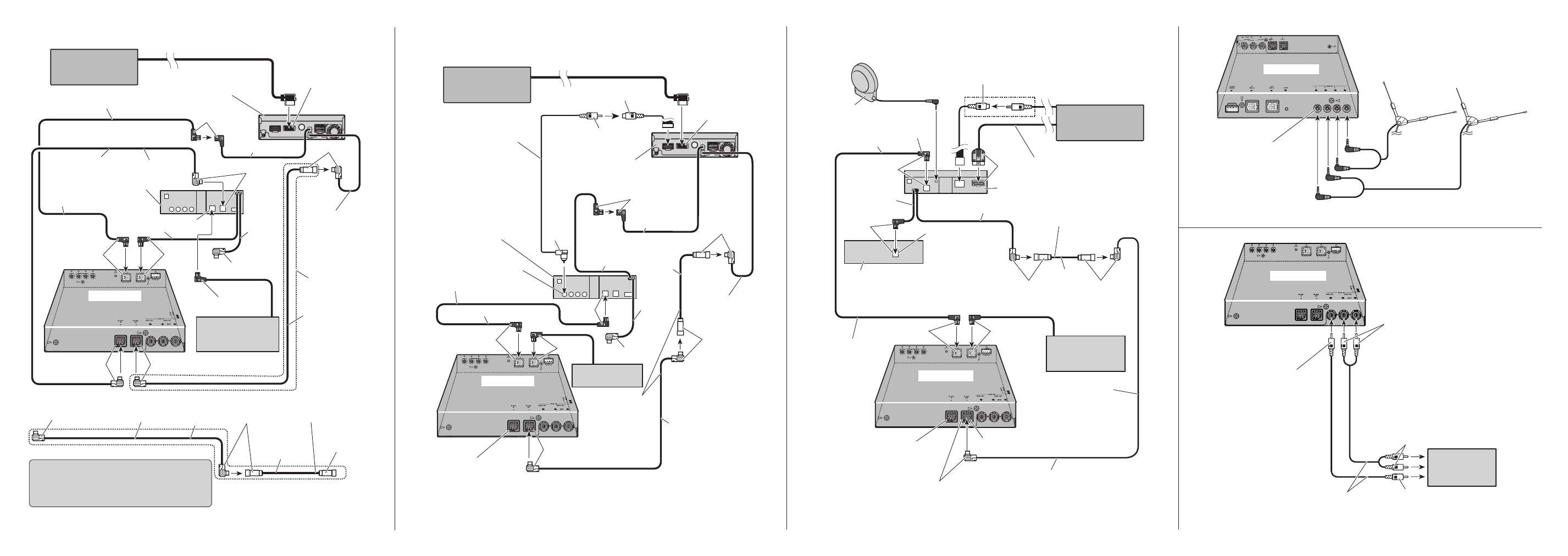
6. AV Receiver
(sold separately)
13. AV-BUS cable
12. Black
14. Not used.
18. AV-BUS Output (Black)
9. IP-BUS cable
15. This product
8. Blue
13. AV-BUS
cable
16. AV-BUS cable
(supplied)
3. 26 pin RGB input
(Yellow)
1. DVD Navigation Unit
(sold separately) II > 17. Not used. In case of the 4. RCA cable (supplied with DVD player) 8. Blue 5. Yellow 5. Yellow 10. DVD player (sold separately) 9. IP-BUS cable 12. Black 8. Blue 7. IP-BUS cable (supplied) 3 m 3 m 8. Blue 2. Yellow (video input) (VIDEO INPUT) 11. Yellow (video output) (FRONT VIDEO OUTPUT) 19. Muli-CD player (sold separately) 50 cm 2. AV Receiver (sold separately) 10. AV-BUS cable 7. Black 11. Not used. 7. Black 5. Blue 6. IP-BUS cable 9. DVD player (sold separately) 15. AV-BUS Output (Black) 4. IP-BUS cable (supplied) 6. IP-BUS cable 12. This product 8. AV-BUS cable (supplied) 5. Blue 10. AV-BUS cable 13. AV-BUS cable (sold separately) 3 m 3 m 3. 26 pin RGB input (Yellow) *1 7. Black 14. AV-BUS Input (Blue) 1. DVD Navigation Unit (sold separately) II > 5. Blue 7. Black 7. Black 8. AV-BUS cable (supplied) 8. AV-BUS cable (supplied) 3 m 50 cm 17. When a DVD player (e.g. SDV-P7) is not used, use the AV-BUS cable (supplied) instead of 16. Multi-CD player (sold separately) 5. Blue 5. Blue 1. Voice guidance speaker 2. Yellow (VIDEO INPUT) *2 4. RGB cable 5. Red 6. Blue 7. Display unit 8. IP-BUS cable 9. AV-BUS cable 12. Head unit with IP-BUS 13. Black 13. Black 11. AV-BUS cable (supplied) 14. IP-BUS cable 18. This product 17. AV-BUS output (Black) 11. AV-BUS cable 3 m 3 m 6. Blue 15. Multi-CD player 3. DVD Navigation Unit II > 6. Blue 13. Black 50 cm 6. Blue 10. IP-BUS input (Blue)*2 16. Not used. In case of this connection, 3. TV antenna inputs Connect from 1 in order. 2. TV antenna (sold separately) 1. This Product Fig. 4 Fig. 6 Fig. 7 2. RCA video output (Yellow) 3. RCA audio output (White, Red) 4. RCA cables 6. To video input 5. To audio inputs 7. Display with RCA input jacks 1. This Product Fig. 8 Fig. 5
connection, this
jack is not used.
the AV-BUS cable
in the figure.
(supplied with the Display)
(supplied with the Display)
(sold separately)
(supplied)
(supplied)
(sold separately)
(sold separately)
If you are using
the AVX-7300 display,
connect the IP-BUS
input (blue) to another
IP-BUS input (blue).
this jack is not used.
(e.g. AN-G3)
Abb. 4
Afb. 4
Abb. 6
Afb. 6
Abb. 7
Afb. 7
(sold separately)
Abb. 8
Afb. 8
Abb. 5
Afb. 5