Bunn TU5Q User Manual
Page 14
Page 14
SERVICE (cont.)
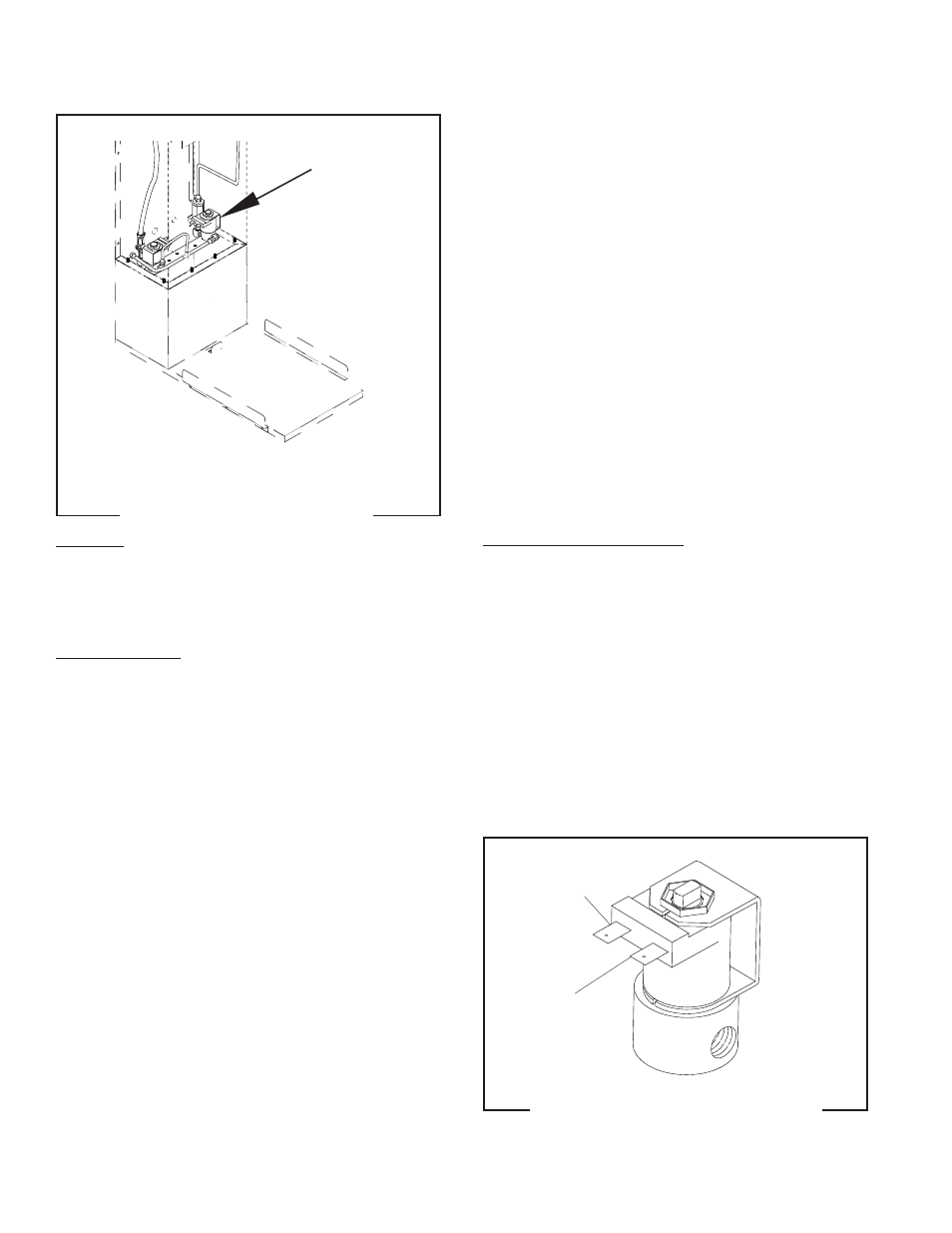
BREW SOLENOID VALVE
FIG. 4 BREW SOLENOID VALVE
Location:
The brew solenoid is located inside the upper rear
access panel, on the left side of the bracket when
looking at it from the rear of the brewer
.
Test Procedures:
1. Disconnect the brewer from the power source.
2. Disconnect the white/violet and white/green wires
from the solenoid valve. With the ON/OFF switch
in the "ON" position press the start switch.
3. With a voltmeter, check the voltage across the
white/violet and white/green wires. Connect the
brewer to the power source. The indication must
be:
a) 120 volts ac for 2-wire 120 volt models.
b) 120 volts ac for 3-wire 120/208 and 120/240
volt models.
4. Disconnect the brewer from the power source.
If voltage is present as described, proceed to #5
If voltage is not present as described, refer to
Wiring
Diagram
and check brewer wiring harness.
5. Check for continuity across the solenoid valve coil
terminals.
If continuity is present as described, reconnect the
white/violet from the brew timer and white/green wire
from the brew timer.
If continuity is not present as described, replace the
solenoid valve.
6. Check the solenoid valve for coil action. Connect
the brewer to the power source. With ON/OFF
switch in the "ON" position press start switch and
listen carefully in the vicinity of the solenoid valve
for a "clicking" sound as the coil magnet attracts.
7. Disconnect the brewer from the power source.
If the sound is heard as described and water will not
pass through the solenoid valve, there may be a block-
age in the water line before the solenoid valve or, the
solenoid valve may require inspection for wear, and
removal of waterborne particles.
If the sound is not heard as described, replace the
solenoid valve.
Removal and Replacement:
1. Remove all wires from solenoid valve.
2. Turn off the water supply to the brewer.
3. Disconnect the water lines to and from the sole-
noid valve.
4. Remove the two #10-32 slotted-head screws hold-
ing the solenoid valve to the bracket.
5. Securely install the new solenoid valve to the
bracket.
6. Securely fasten the water lines to and from the
solenoid valve.
7. Refer to the Fig. 5 when reconnecting the wires.
FIG. 5 SOLENOID VALVE TERMINALS
P1799
WHI/GRN to
Brew Timer TL4
WHI/GRN to
Dilution Solenoid
WHI/VIO to
Brew Timer TL1
10777 041500
4
2
3
1
MIN
UTES
MINUT
ES
BUNN-O-MA
TIC
P/N 05791-0006 120 VAC
5
3
6
4
7
5
6
6
7
8
P2146.35