Iii. installation, Map of the asus motherboard, 4asus p/i-ap55tv user’s manual – Asus P/I-AP55TV User Manual
Page 10: Map of board) iii. inst alla tion
4
ASUS P/I-AP55TV User’s Manual
III. INSTALLATION
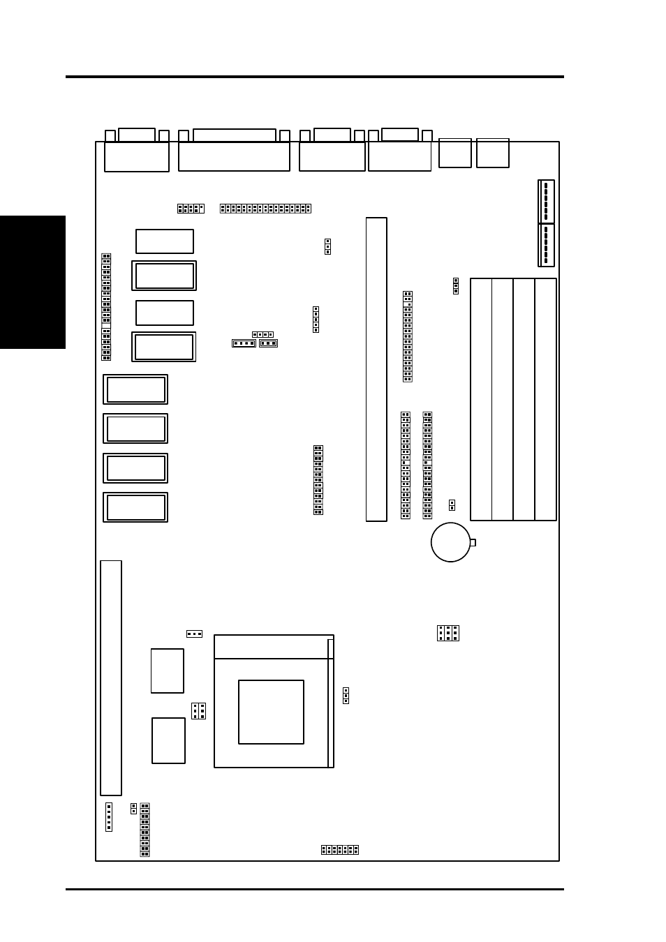
Map of the ASUS Motherboard
JP14
JP15
JP
16
BUS FREQ
Infrared Con.
Primary IDE
Secondary IDE
Raiser Card Connector
SIMM Socket 1 (Bank 0)
SIMM Socket 2 (Bank 0)
SIMM Socket 3 (Bank 1)
SIMM Socket 4 (Bank 1)
CPU ZIF Socket 7
Board Power Input
P8
P9
Audio Connector
USB
AMC Connector
Panasonic CD In
Mitsumi CD In
Floppy Drives
W
ave T
able
Upgrade
JP17
L2 Cache (512/256)
12V Fan Power
JP1
8
JP1
9
FREQ Ratio
Case Connectors
IDE LED
JP24
CPU Voltage
JP22
JP25
JP20
JP21
JP23
JP26
512KB DRAM
512KB DRAM
Upgrade Socket
512KB DRAM
512KB DRAM
Upgrade Socket
512KB DRAM
Upgrade Socket
512KB DRAM
Upgrade Socket
512KB DRAM
Upgrade Socket
512KB DRAM
Upgrade Socket
Volume Control
Gnd
Up
Down
Gnd
Gnd
Audio (En/Dis)
JP6
Boot Block Write (En/Dis)
CR2032
3 Volts
Lithium
Button Cell
Battery Test/
Clear CMOS
JP4A
JP5A
PS/2
Keyboard
PS/2
Mouse
Parallel Connector
Serial COM1
Serial COM2
VGA Output
256/512KB OnBoard L2 Cache
Pipelined Burst Level 2 Cache Expansion Slot
Sony CD In
(Map of Board)
III. INST
ALLA
TION