Lenovo G710 Notebook User Manual
Page 51
Lenovo G700/G710
-
47
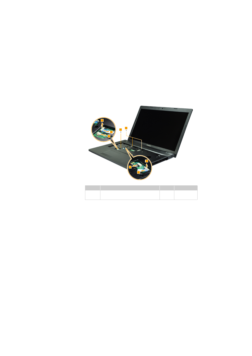
Figure 9. Removal steps of keyboard bezel (continued)
Detach the touchpad button board and power board connectors in the direction
shown by arrows
and
,unplug microphone and speakers connectors by
arrow
. Remove three screws
.
When installing:
Make sure that all the connectors are attached firmly.
Step
Screw (quantity)
Color
Torque
M2 × 6 mm, flat-head, nylok-coated (3)
C bracket to C
Black
1.5 ~ 2.0 kgfcm
c
d
e
f
6
6
3
4
5
3
4
5
f
This manual is related to the following products:
See also other documents in the category Lenovo Notebooks:
- IdeaPad S10 (138 pages)
- IdeaPad S10 (7 pages)
- IdeaPad U455 (142 pages)
- IdeaPad Y550 (2 pages)
- IdeaPad Y550 (138 pages)
- IdeaPad S10-3s (81 pages)
- IdeaPad S10-3s (130 pages)
- IdeaPad S10-3s (2 pages)
- IdeaPad Y530 (152 pages)
- IdeaPad Y530 (2 pages)
- IdeaPad Y510 (77 pages)
- IdeaPad U450 (142 pages)
- IdeaPad U450 (2 pages)
- IdeaPad Y330 (148 pages)
- IdeaPad Y330 (2 pages)
- IdeaPad S10-2 (140 pages)
- IDEAPAD Y560P (145 pages)
- IdeaPad S10-3 FR (12 pages)
- IdeaPad S10-3c (128 pages)
- IdeaPad S10-3c (88 pages)
- IdeaPad S10-3c (16 pages)
- IdeaPad S10-3c (4 pages)
- IDEAPAD Y570 (51 pages)
- IDEAPAD Y570 (15 pages)
- IDEAPAD Y570 (103 pages)
- IdeaPad S100 (41 pages)
- IdeaPad S100 (79 pages)
- IdeaPad U450p (136 pages)
- IdeaPad U550 (2 pages)
- IdeaPad U550 (144 pages)
- IdeaPad U330 (135 pages)
- IdeaPad U330 (2 pages)
- IdeaPad S205 (2 pages)
- IdeaPad S205 (46 pages)
- IdeaPad S205 (81 pages)
- IdeaPad S205 (10 pages)
- 3000 G230 (140 pages)
- IdeaPad V360 (58 pages)
- IdeaPad V360 (2 pages)
- IdeaPad V360 (87 pages)
- IdeaPad U260 (77 pages)
- IdeaPad U260 (42 pages)
- IdeaPad U150 (140 pages)
- IdeaPad U460s (88 pages)
- IdeaPad U460s (143 pages)