Lenovo ideapad s400 hardware maintenance manual – Lenovo IdeaPad S400u Notebook User Manual
Page 54
Lenovo IdeaPad S400 Hardware Maintenance Manual
50
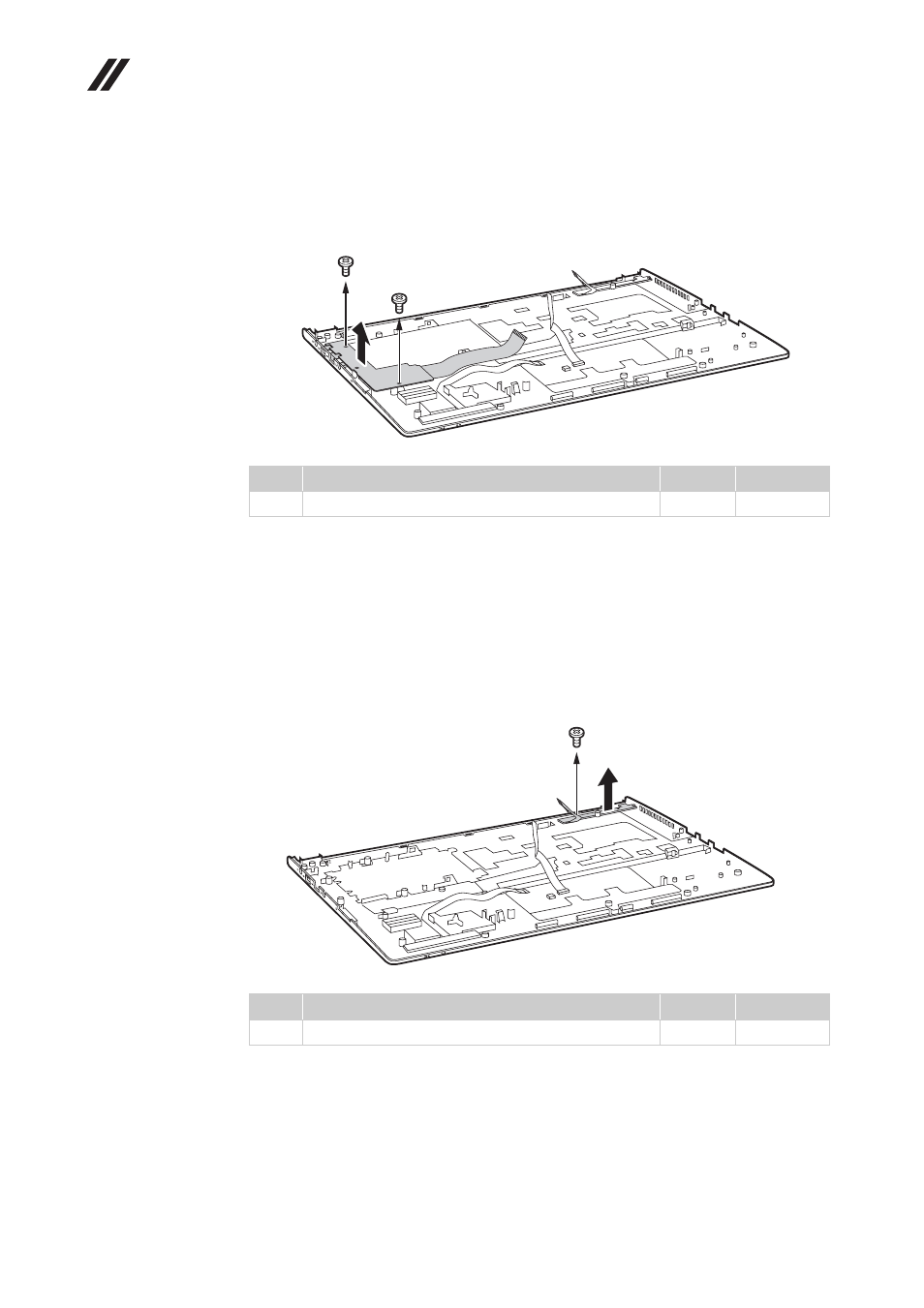
Figure 9. Speakers, base cover, USB board, power assembly and power board (continued)
Remove two screws
, and then remove the USB board in the direction shown
by arrow
.
When installing:
When attaching the USB board to the base cover, adjust the
placement of the USB and headphone jacks as shown , and make sure that both
of the USB and the headphone jacks are attached to the holes on the base cover
as shown. Improper placement of the jacks might cause a damage.
Remove the screw
to lift the power board in the direction shown by arrow
.
Step
Screw (quantity)
Color
Torque
M2 × 3 mm, flat-head, nylok-coated (2)
Silver
1.85 kgfcm
Step
Screw (quantity)
Color
Torque
M2 × 3 mm, flat-head, nylok-coated (1)
Black
1.85 kgfcm
d
e
e
d
d
a
f
g
g
f
a