1150 system board assembly – Lenovo M490s notebook User Manual
Page 65
1150 System board assembly
For access, remove these FRUs in order:
•
“1010 Battery pack” on page 42
•
“1020 Bottom slot cover” on page 42
•
“1030 Memory modules” on page 43
•
“1040 Hard disk drive assembly” on page 45
•
“1050 PCI Express Mini Card for wireless LAN” on page 46
•
“1060 mSATA solid-state drive” on page 47
•
“1070 Backup battery” on page 48
•
•
“1110 Fingerprint board bracket and fingerprint board” on page 52
•
“1120 Thermal module assembly” on page 54
Important notice for replacing the system board
When replacing the system board, observe the following guidelines:
• Do not drop a system board on a bench top that has a hard surface, such as metal, wood, or composite.
• Do not apply any excessive force to a system board.
• Avoid rough handling of any kind.
• Avoid bending a system board or hard pushing to prevent cracking at each Ball Grid Array (BGA) chipset.
• When you put a system board down, be sure to put it only on a padded surface such as an ESD mat
or a corrugated conductive surface.
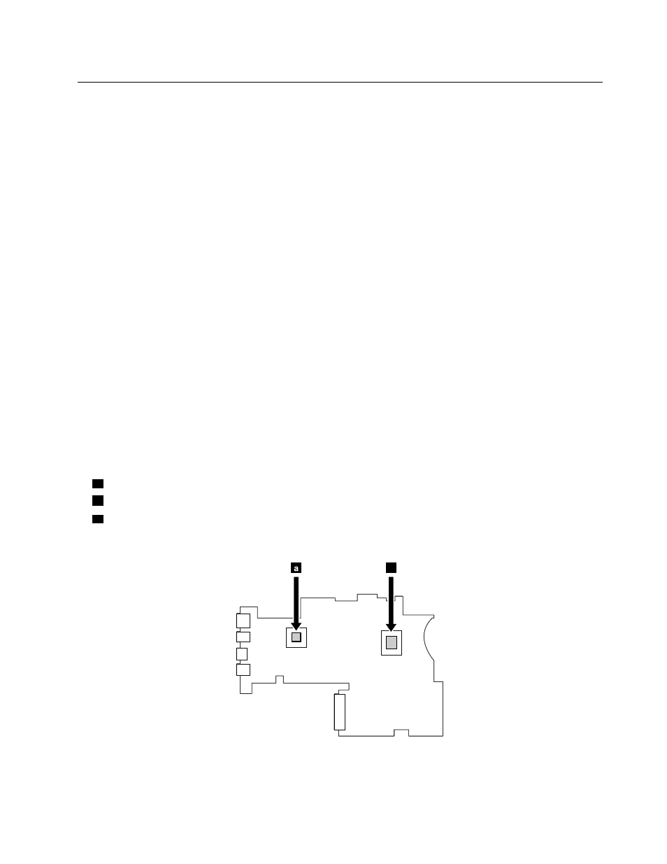
Locating major sensitive components on the system board
Attention: The following components mounted on a system board are extremely sensitive. Improper
handling of a system board can cause damage to the following components, and might cause a system
malfunction. When you service the system board, avoid any kind of rough handling.
a
Platform Controller Hub (PCH)
b
Microprocessor
c
Graphics chip (for discrete graphics models)
For models with an integrated thermal module assembly
a
b
Chapter 8
.
Removing or replacing a FRU
59