Lenovo B40-30 Notebook User Manual
Page 53
Lenovo B40-30/B40-45/B40-70
49
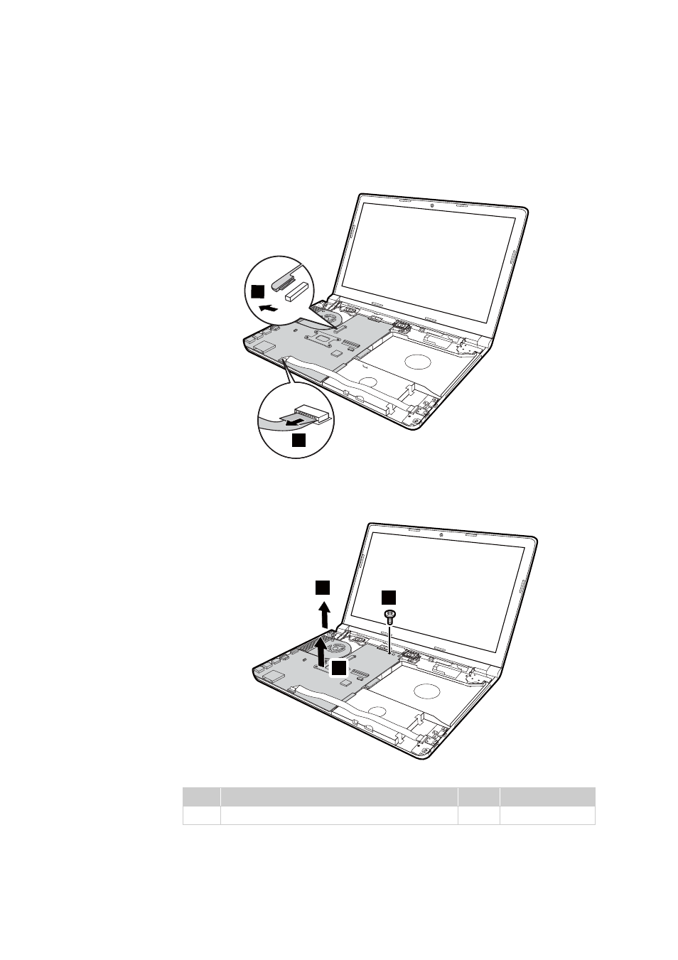
Figure 11. Removal steps of system board (continued)
Disconnect the USB board connector in the direction shown by arrow
. Then
disconnect the EDP connector in the direction shown by arrow
.
Remove the screw
. Pull the DC‐IN connect from its cavity in the direction by
arrow
. Then remove the system board in the direction by arrow
.
When installing:
• Make sure USB, HDMI, and the VGA of the system board attached into its
holes on the base properly. Improper placement of the jacks may cause
damage.
• Make sure that the connectors are attached firmly to the system board.
Step
Screw (quantity)
Color Torque
M2.5 x 4 mm, flat‐head, nylok‐coated (1)
Black
2.0~2.5kgf.cm
b
c
2
3
d
e
f
4
5
6
7
d
d
This manual is related to the following products: