Vollrath 219-02 User Manual
Page 18
10
3.7
ASSEMBLY OF MIX PUMP
CAUTION
DO NOT FORCE PARTS, THEY FIT TOGETHER
EASILY WHEN PROPERLY INSTALLED.
Haynes sanitary lubricant or liquid equivalent must be
used to lubricate all “O”-rings, piston shaft and bore of
cylinder body.
A. Place manifold “O”-ring (9) onto manifold (5) and
lubricate lightly. Place manifolds connector “O”-ring
(8) onto manifold (5) and lubricate. Place manifold
(5) into pressure switch. Position locking plate washer
(7) and secure with two wing nuts (6) finger tight.
Connect tubing (11) to quick connect (4) and tighten
hose clamp (10) finger tight. Connect quick connect
(4) to manifold (5). (See Fig. 6)
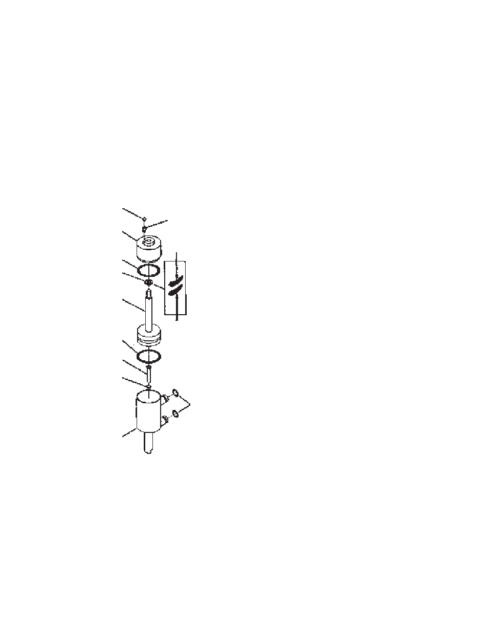
B. Install air inlet check valve (30) into cylinder top (31).
Do not lubricate. Install air inlet retainer (29) into air
inlet valve. Push into place. Check quad ring (33) for
excessive wear and replace if necessary . Spray a
thin film of lubricant in bottom of cylinder top (31).
NOTE
Quad ring must not be twisted.
Install quad ring (33) and rotate one full turn to improve
sealing. Place “O”-ring (35) onto piston shaft (34) and
“O”-ring (32) onto cylinder top (31). Spray a thin film
of lubricant onto the two “O”-rings, piston shaft and
cylinder walls. Position cylinder top (31) over piston
shaft (34). Place “O”-ring (37) onto mix inlet valve (36)
and insert inlet valve (36) into cylinder (28). Assemble
cylinder top (31) and piston (34) into cylinder (28)
and push piston fully down.
C. Place “O”-ring (26) onto mix transfer tube bottom (25)
and lubricate. Place mix transfer tube bottom (25)
into air transfer tube top (24). (See Fig. 9)
On hopper models: place mix transfer tube “O”-ring
(23) onto bottom of mix transfer tube (25) and lubricate
lightly. Position small end of two air/mix outlet springs
(22) onto two air/mix outlet valves (21) and insert
into mix transfer tube. Place valve retainer “O”-ring
(18) onto valve retainer (17). Insert safety valve (20),
spring (19) and valve retainer (17) into top hole of
mix transfer tube. (See Fig. 9)
D. Holding valve retainer firmly in place with thumb and
forefingers, join mix transfer tube (15) to pump cylinder
(16) as shown. (See Fig. 8)
Figure 11. Mix Pump Assembly
30
32
33
34
35
36
37
28
27
29
31
GOOD
REPLACE