Assembly, Connect shift rod (see fig. 6), Remove tiller from crate – Ariens 90102800 User Manual
Page 5: Check tire pressure, Handle height, Install handle (see figs. 3, 4, and 5)
5
ASSEMBLY
Fig. 4
Fig. 5
hand
les_
34
SILVER
HANDLE
LOCK
FLAT
WASHER
HANDLE BASE
GEARCASE
SLOT
REAR
CARRIAGE
BOLT
HANDLE
LOCK
LEVER
LOCKNUTS
PIVOT
BOLT
Fig. 3
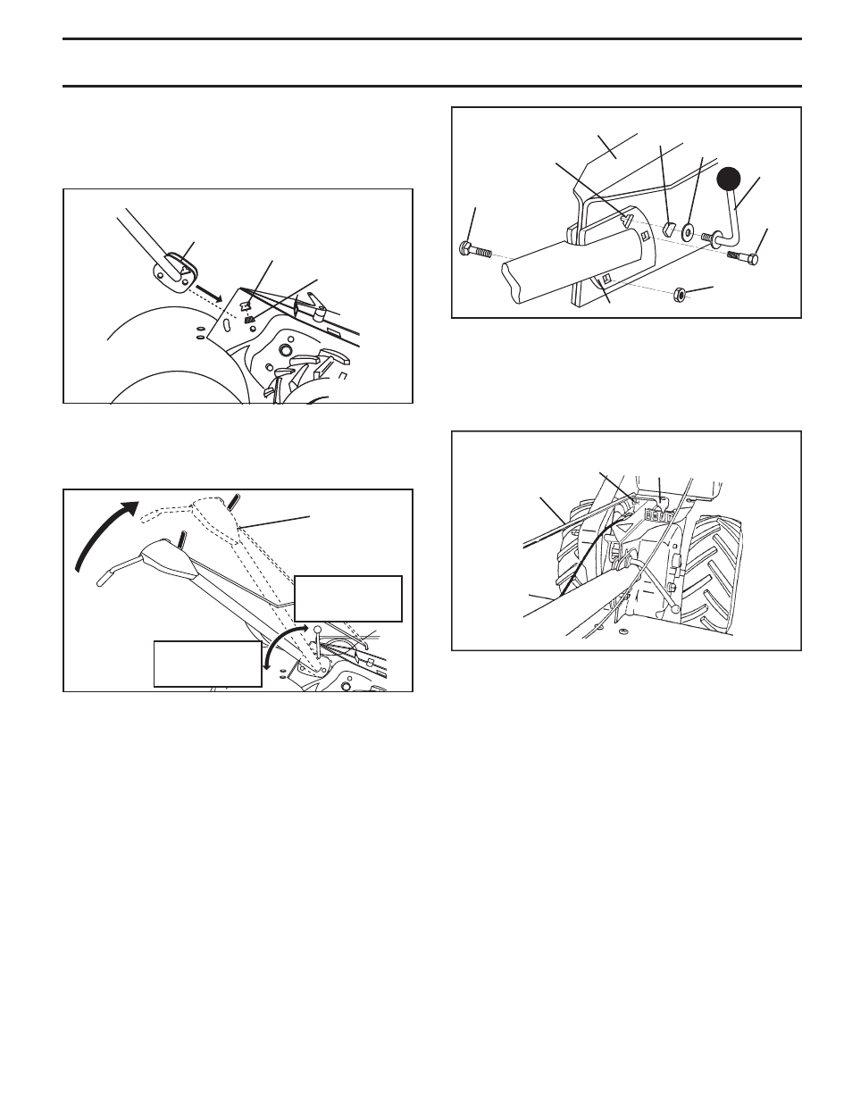
CONNECT SHIFT ROD (See Fig. 6)
• Insert end of shift rod into hole of shift lever indicator.
• Insert hairpin clip through hole of shift rod to secure
with bend of clip on right side.
REMOVE TILLER FROM CRATE
•
Ensure shift lever indicator is in “N” position (See Fig. 6).
•
Tilt tiller forward by lifting handle. Separate cardboard
cover from leveling shield.
•
Rotate tiller handle to the right and pull tiller out of carton.
CHECK TIRE PRESSURE
The tires on your unit were overinflated at the factory for
shipping purposes. Correct and equal tire pressure is
important for best tilling performance.
• Reduce tire pressure to 20 PSI (1.4 kg/cm
2
).
HANDLE HEIGHT
•
Handle height may be adjusted to better suit operator.
(See “TO ADJUST HANDLE HEIGHT” in the Service
and Adjustments section of this manual.)
Fig. 6
SHIFT
ROD
HAIRPIN
CLIP
SHIFT
LEVER
INDICATOR
HANDLE ASSEMBLY
"UP" POSITION
LOOSEN HANDLE
LOCK LEVER TO
MOVE
TIGHTEN HANDLE
LOCK LEVER TO
HOLD
•
Grasp handle assembly. Hold in “up” position. Ensure
handle lock remains in gearcase notch. Slide handle
assembly into position.
INSTALL HANDLE (See Figs. 3, 4, and 5)
• Insert one handle lock (with teeth facing outward) in
gearcase notch. (Apply grease on smooth side of
handle lock to aid in keeping lock in place until handle
assembly is lowered into position.)
•
Rotate handle assembly down. Insert rear carriage bolt
first, with bolt head on L.H. side of tiller and loosely
assemble locknut (See Fig. 5).
• Insert pivot bolt in front part of plate and tighten.
•
Cut down remaining corners of carton and lay panels flat.
• Lower the handle assembly. Tighten nut on carriage
bolt so handle moves with some resistance. This will
allow for easier adjustment.
•
Place flat washer on threaded end of handle lock lever.
• Insert handle lock lever through handle base and
gearcase. Screw in handle lock lever just enough to
hold lever in place.
• Insert second handle lock (with teeth in ward) in the
slot of the handle base (just inside of washer).
• With handle assembly in lowest position, securely
tight en handle lock lever by rotating clockwise. Leav ing
handle assembly in lowest position will make it easier
to remove tiller from carton.
HANDLE
LOCK
HANDLE
ASSEMBLY
GEARCASE
NOTCH
VIEWED FROM R.H. SIDE OF TILLER