Service and adjustments, Tiller – Ariens 90102800 User Manual
Page 14
14
TILLER
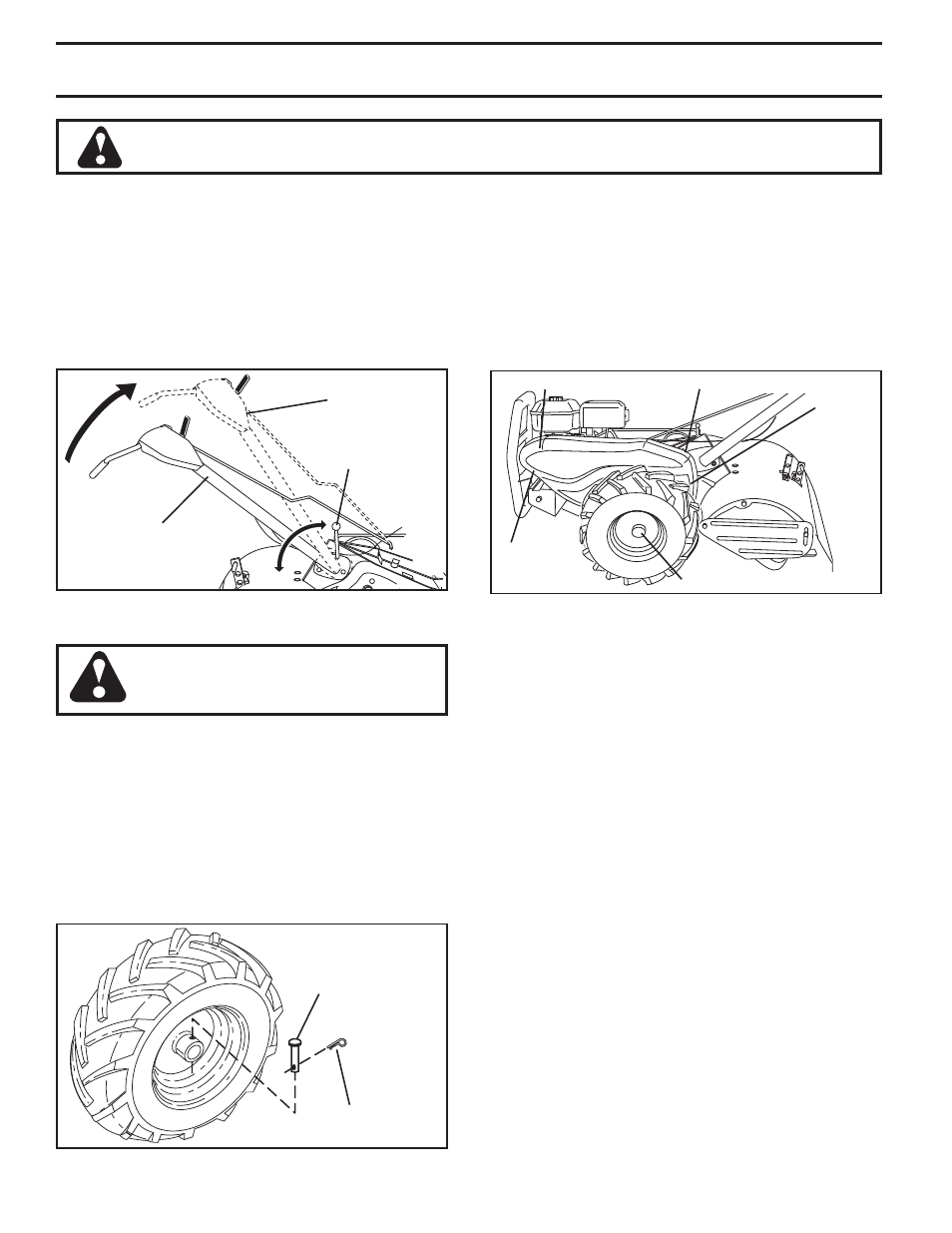
TO ADJUST HANDLE HEIGHT (See Fig. 23)
Select handle height best suited for your tilling conditions.
Handle height will be different when tiller digs into soil.
• First loosen handle lock lever.
•
Handle can be positioned at different settings between
“HIGH” and “LOW” positions.
• Retighten handle lock lever securely after adjusting.
Fig. 23
Fig. 24
Fig. 25
TO REMOVE BELT GUARD (See Fig. 25)
NOTE: For ease of removal, remove hairpin clip and
clevis pin from left wheel. Pull wheel out from tiller about
1 inch.
• Remove two (2) screws from side of belt guard.
•
Remove hex nut and washer from bottom of belt guard
(located behind wheel).
• Pull belt guard out and away from unit.
• Replace belt guard by reversing above procedure.
TIRE CARE
CAUTION: When mounting tires, un-
less beads are seated, over in fla tion
can cause an explosion.
• Maintain 20 pounds of tire pressure. If tire pressures
are not equal, tiller will pull to one side.
• Keep tires free of gasoline or oil which can damage
rubber.
TO REMOVE WHEEL (See Fig. 24)
• Place blocks under trans mis sion to keep tiller from
tipping.
• Remove hairpin clip and clevis pin from wheel.
• Remove wheel and tire.
• Repair tire and reassemble.
CLEVIS PIN
HAIRPIN CLIP
CAUTION: Disconnect spark plug wire from spark plug and place wire where it cannot come into
contact with plug.
SCREW
AND
WASHER
HEX NUT
AND
WASHER
(LOCATED
BEHIND
TIRE)
SCREW AND WASHER
BELT GUARD
HAIRPIN CLIP AND CLEVIS PIN
TO REPLACE GROUND DRIVE BELT
(See Figs. 25 and 26)
• Remove belt guard as described in “TO REMOVE
BELT GUARD”.
•
Remove old belt by slipping off engine pulley first then
remove from transmission pulley.
• Place new belt in groove of transmission pulley and
into engine pulley. BELT MUST BE IN GROOVE ON
TOP OF IDLER PULLEY. NOTE POSITION OF BELT
TO GUIDES.
• Check belt adjustment as described below.
• Replace belt guard.
• Reposition wheel and replace clevis pin and hairpin
clip.
GROUND DRIVE BELT ADJUSTMENT
(See Fig. 26)
For proper belt tension, the extension spring should have
about 5/8 inch (16 mm) stretch when Tine control are in
“EN GAGED” position. This tension can be attained as
fol lows:
• Loosen cable clip screw securing the drive control
cable.
• Slide cable forward for less tension and rearward for
more tension until about 5/8 inch (16 mm) stretch is
obtained while the Tine control are engaged.
• Tighten cable clip screw securely.
SERVICE AND ADJUSTMENTS
HANDLE
(LOW POSITION)
HANDLE LOCK
LEVER
HANDLE
(HIGH POSITION)