Dc ac – Pfannenberg PATROL PA X 20 Series User Manual
Page 9
085 501 946j
30305-004j
9
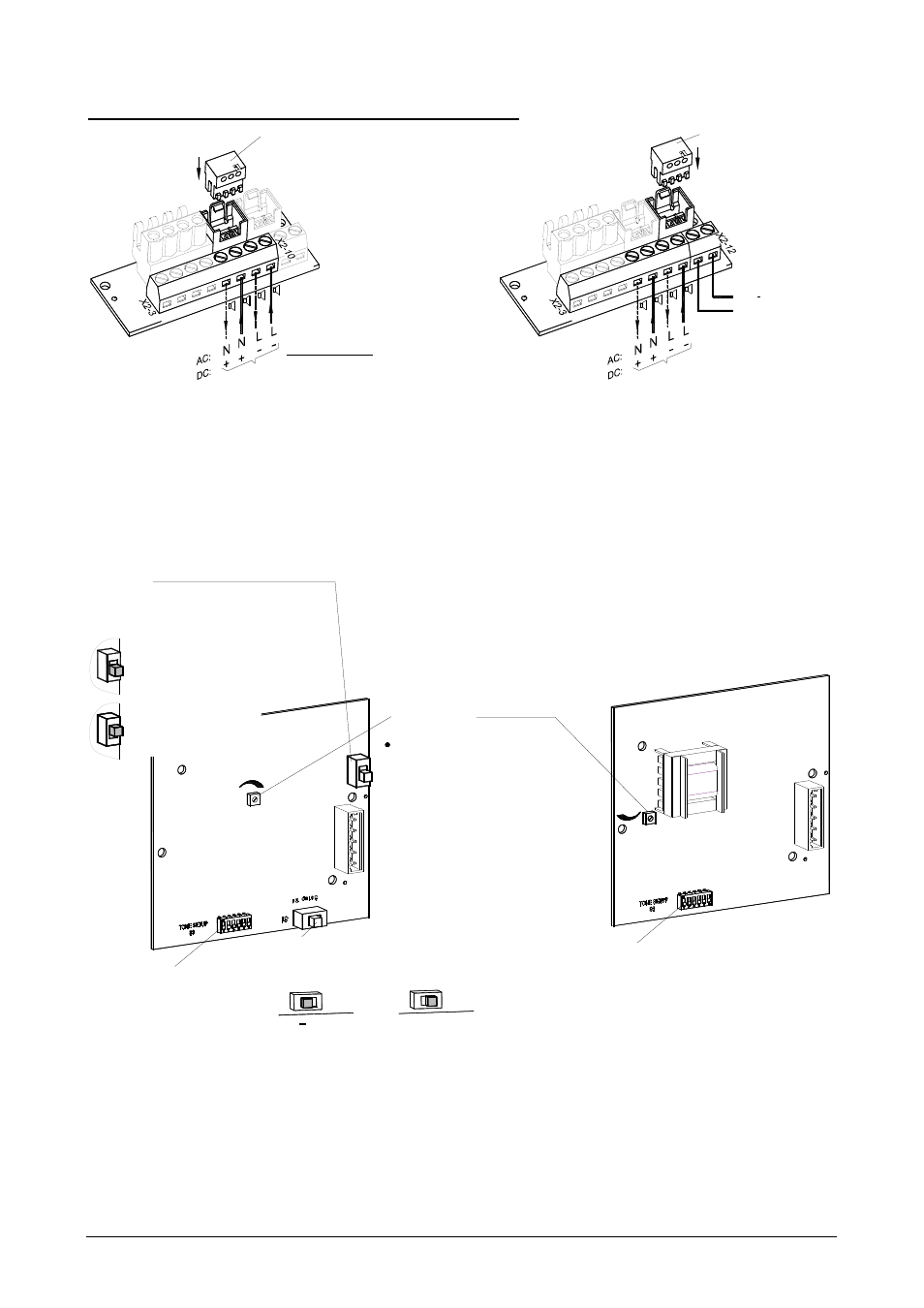
Terminal for operating voltage - Sounder-beacon combination:
X2
Sounder and Beacon
Operating voltage
Connection for
+N
-L
X3
X4
C2
C1
C2
C1
Plug from beacon circuit board
+N
-L +N
-L
Operating voltage
for the sounder
X4
X3
X2
for the beacon
Operating voltage
D
C
:
A
C
:
+
C2
C1
C2
C1
L
N
+N
-L
+N
-L
-L
+N
Plug from beacon circuit board
Common connection of
Separate connection of
beacon and sounder
beacon and sounder
(Delivery status)
The desired tone can be selected using the tone selector switch S3 (on the driver circuit board). The available
tones are described in the tone table in the appendix.
After establishing the supply voltage the tone is generated.
Driver circuit board of sounder (located in the upper section):
with reverse polarity protection
(with rectifier)
Factory setting
without reverse polarity protection
(without rectifier)
DC
AC
S2
S3
S3
S2
S1
+
+
-
+
-
(Bridging
of blocking diode)
Volume control
Note:
To be EN54-3 compliant, the volume
control has to be set to
the following position:
Tone selector switch
(Selection of polarity of the
control voltage for C1 and C2)
Factory setting
Tone selector switch
PA 10: Maximum position
PA 20: in the secured
factory setting position
To be UL/cUL compliant, the volume
control for PA 20 and PA X 20..
has to be set to the secured
factory setting position