Taking into operation – Pfannenberg PATROL PA X 5 Series User Manual
Page 8
085 501 945d
30304-004d
8
Taking into operation
Safety notes:
- Installation must be carried out by an electrician in compliance with the latest codes and regulations.
- Danger: High voltage may be present.
- Prior to opening, it must be ensured that no voltage is applied to the device.
- Before electrical connection, the supply voltage on the type plate is to be checked. The wrong operating voltage
can lead to damages or to the destruction of the equipment.
- During installation it must be ensured that the connection cables are secured against tension and distortion.
Please observe: The devices are not designed for portable use.
- CAUTION: When making installation, route field wiring away from sharp projections, corners and internal compo-
nents.
- The opening of the bell mouth must not point upwards, especially in the case of use outdoors or in a particularly
dusty environment.
- The function of the unit is only guaranteed if the upper and lower section is joined correctly.
When using the sounder –beacon combination (PA X 5-05/ PA X 5-10):
- In order to prevent detriment to sight, continuously looking directly in the activated light is to be avoided.
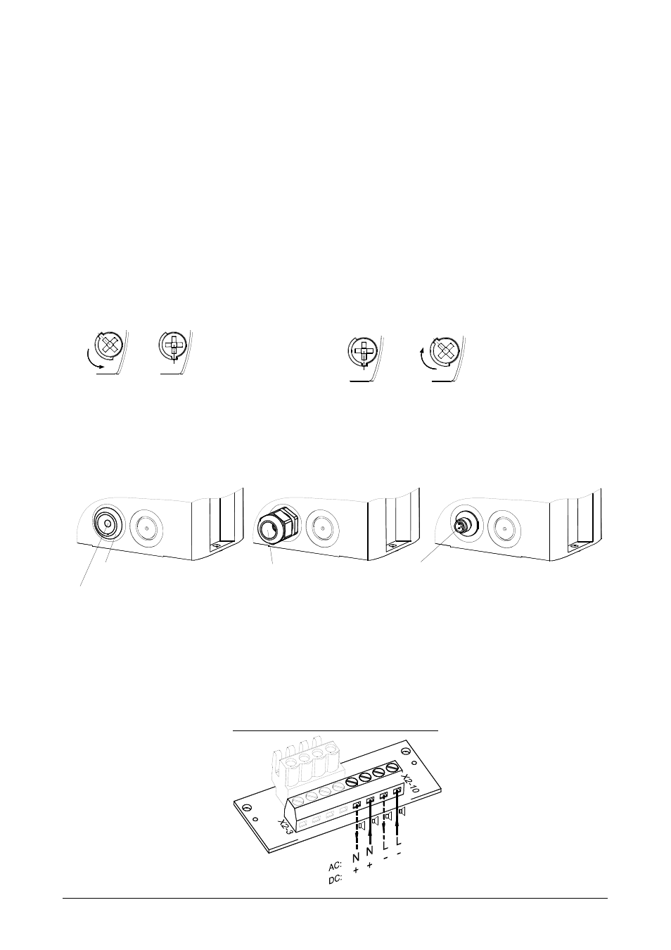
Opening the housing:
Closing the housing
3/8
1.
2.
3/8
1.
2.
The unit is not closed when delivered.
Sealing plugs for the housing screws are available as accessories.
Cable gland entries
To guarantee the specified protection type, cable grommets with a protection type of IP 66 are to be installed at the
openings provided for this purpose. The supplied diaphragm nipple can be replaced with a cable gland or with an M12
plug connection with a flange measurement of M20.
Cable gland IP 66
(provided)
the remaining membrane break-out.
After pushing through the cable remove
Diaphragm nipple IP 66
M12 plug connector IP 66
(for low voltage versions)
Circuit board for electrical connection (located in the base section):
Electrical connection and tone selection using external control C1 and C2
Terminal for operating voltage - Sounder:
Connection for
+N
X2
Operating voltage
-L
C2
C1
C2 C1
+N
-L
By loosing the four
cover screws, the upper
section can be re-
moved.
The housing is closed
by turning the cover
screws to the limit
position until the
housing locks into
place.