MSI Keeper 945GME V2.1 User Manual
Page 34
M S-9641 M ainboard
2-22
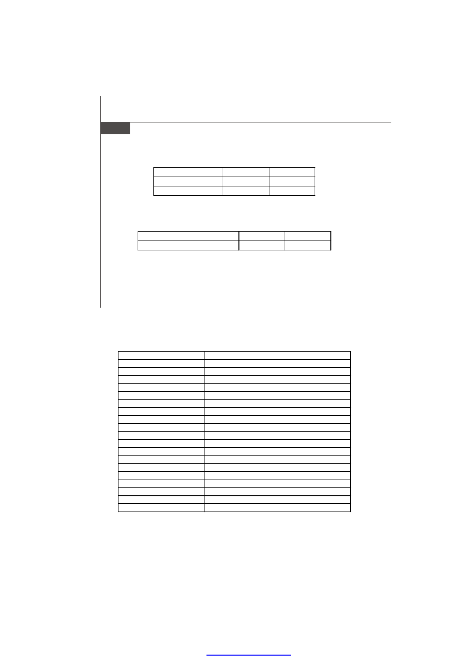
Method 1: GPIO control Bypass (GPIO Mode)
ByPass
Normal
SB GPIO38(Relay1)
High
Low
SB GPIO39(Relay2)
High
Low
Note: GPIO Mode has two configuration. One is GPIO38,39 controlling together; the
other is GPIO38,39 controlling individually.
Method 2: LPC Control Bypass (LPC M ode)
LPC I/O Address: 5E
ByPass
Normal
Bit[0..3] corresponds to LAN [1..4]
High
Low
Note: bit 0 = 1, change LAN 1, 2 to bypass,
bit 0 = 0, change LAN 1, 2 to normal (power on status)
bit 1 = 1, change LAN 3, 4 to bypass,
bit 1 = 0, change LAN 3, 4 to normal (power on status)
bit 2 = 1, change LAN 1, 2 to bypass,
bit 2 = 0, change LAN 1, 2 to normal (power off status)
bit 3 = 1, change LAN 3, 4 to bypass,
bit 3 = 0, change LAN 3, 4 to normal (power off status)
Sample code (Method 1: GPIO Mode)
Set GPIO38, 39 to Control LAN
GPIO38,39 control together
mov al,10h
;GPIO38,39 control By pass (BIT4=1,BIT 7=0)
mov dx,005eh
; if GPIO38,39 control dividually, set BIT 4=1, BIT7=1)
out dx,al
; Choose GPIO Mode and GPIO 38 ,39 together control configration
mov dx,480h + 30h
;Select SB GPIO
in eax,dx
or eax,0C0h
;Select GPIO 38,39
out dx,eax
mov dx,480h + 34h
;Control IN/OUT
in eax,dx
and eax,Not 0C0h
out dx,eax
mov dx,480h + 38h
in al,dx
and al,not 11000000b
;Enable GPIO 38,39
or al,11000000b
out dx,al
PDF created with pdfFactory Pro trial versi