Chapter 3, Important – MSI PH67S-C43 (B3) User Manual
Page 49
BIOS Setup
MS-7673
Chapter 3
3-9
BIOS Setup
MS-7673
Chapter 3
tRFC
Ths settng determnes the tme RFC takes to read from and wrte to a memory
cell.
tWR
Mnmum tme nterval between end of wrte data burst and the start of a precharge
command. Allows sense amplfiers to restore data to cells.
tWTR
Mnmum tme nterval between the end of wrte data burst and the start of a col-
umn-read command. It allows I/O gatng to overdrve sense amplfiers before read
command starts.
tRRD
Specfies the actve-to-actve delay of dfferent banks.
tRTP
Tme nterval between a read and a precharge command.
tFAW
Ths tem s used to set the tFAW (four actvate wndow delay) tmng.
tWCL
Ths tem s used to set the tWCL (Wrte CAS Latency) tmng.
tCKE
Ths tem s used to set the tCKE tmng.
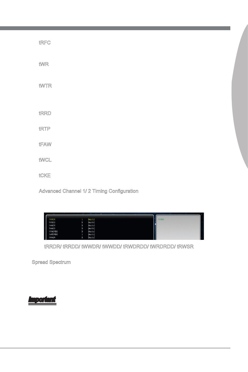
Advanced Channel 1/ 2 Tmng Configuraton
Press
for each channel.
tRRDR/ tRRDD/ tWWDR/ tWWDD/ tRWDRDD/ tWRDRDD/ tRWSR
These tems s used to set the memory tmngs for memory channel 1/ 2.
Spread Spectrum
When the manboard’s clock generator pulses, the extreme values (spkes) of the pulses
create EMI (Electromagnetc Interference). The Spread Spectrum functon reduces the
EMI generated by modulatng the pulses so that the spkes of the pulses are reduced
to flatter curves.
Important
If you do not have any EMI problem, leave the settng at [Dsabled] for optmal system
stablty and performance. But f you are plagued by EMI, select the value of Spread
Spectrum for EMI reducton.
The greater the Spread Spectrum value s, the greater the EMI s reduced, and the
system wll become less stable. For the most sutable Spread Spectrum value, please
consult your local EMI regulaton.
▶
▶
▶
▶
▶
▶
▶
▶
▶
▶
▶
•
•