Cpufan sysfan2, Front panel i/o connectivity design guide – MSI 760GMA-P34 (FX) User Manual
Page 21
2
MS-7641
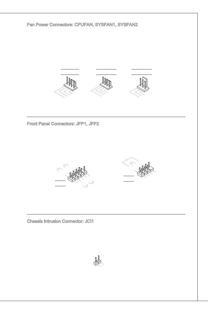
Fan Power Connectors: CPuFAN, SySFAN, SySFAN2
the fan power connectors support system cooling fan with +2V. When connect-
ing the wire to the connectors, always note that the red wire is the positive and
should be connected to the +2V; the black wire is Ground and should be con-
nected to GNd. if the motherboard has a System hardware Monitor chipset on-
board, you must use a specially designed fan with speed sensor to take advantage
of the CPu fan control.
1.Gro
und
2.+1
2V
3.Se
nsor
1.Gro
und
2.+1
2V
3.Se
nsor
4.Co
ntrol
CPuFAN
SySFAN2
1.Gro
und
2.Sp
eed
Contr
ol
3.Se
nse
4.NC
SySFAN
Front Panel Connectors: JFP, JFP2
these connectors are for electrical connection to the front panel switches and
Leds. the JFP is compliant with intel
®
Front Panel i/o Connectivity design
Guide.
1.+
3.-
10.N
o Pin
5.-
Rese
t Sw
itch
HDD
LED
Pow
er Sw
itch
Pow
er LE
D
7.+
9.Re
serve
d
8.-
6.+
4.-
2.+
JFP
1.Gro
und
3.Su
spen
d LE
D
5.Po
wer L
ED
7.No
Pin
8.+
6.-
4.+
2.-
Buzz
er
Spea
ker
JFP2
Chassis intrusion Connector: JCi
this connector connects to the chassis intrusion switch cable. if the chassis is
opened, the chassis intrusion mechanism will be activated. the system will record
this status and show a warning message on the screen. to clear the warning, you
must enter the BioS utility and clear the record.
1.CIN
TRU
2.Gro
und