2 motherboard layout, 2 chapter 2: hardware information, P4sdr-vm – Asus P4SDR-VM User Manual
Page 24: Pci slot 1, Pci slot 2 pci slot 3, 5 cm (9.6in)
2-2
Chapter 2: Hardware information
2.2
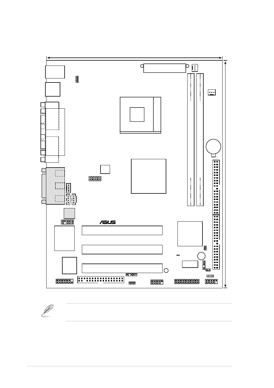
Motherboard layout
The audio features are optional. These components are grayed out in
the above motherboard layout.
FLOPPY1
HPANEL1
IR1
CD1
CPUFAN1
SiS650GL
HOST/
Memory
Controller
PS/2
T: Mouse
B: Keyboard
GAME_AUDIO
Mic
In
Line
Out
Line
In
AUX1
IDELED1
USB2
USBV2
P4SDR-VM
®
SMARTCON1
FPAUDIO1
MODEM
ITE 8707F
Super I/O
2Mbit
Flash
BIOS
PCI Slot 1
ATX Power Connector
Primary IDE
Secondary IDE
Bottom:
USB1
USB2
2 3
0 1
USBV1
SiS961B0
MuTIOL
Media I/0
SPDIF1
ATX12V1
Audio
Codec
ASUS
Mozart
CHASFAN1
CLRRTC1
19.1cm (7.5in)
24.5 cm (9.6in)
Socket 478
PCI Slot 2
PCI Slot 3
COM1
P
ARALLEL
PORT
VGA
USB3
USBV3
DIMM Socket 1 (72-bit, 168-pin module)
DIMM Socket 2 (72-bit, 168-pin module)
CR2032 3V
Lithium Cell
CMOS Power
JF1
FSJ1
LED1
BUZZER
See also other documents in the category Asus Hardware:
- PCI Express Audio Card Xonar DX (70 pages)
- Xonar DX (80 pages)
- Xonar DX (10 pages)
- Xonar D2X (88 pages)
- Xonar D2X (84 pages)
- D2X (88 pages)
- Audio Card Xonar D2X (70 pages)
- ROG Xonar Phoebus (122 pages)
- ROG Xonar Phoebus (72 pages)
- Xonar DSX (26 pages)
- Xonar DSX (29 pages)
- Xonar DGX (33 pages)
- Xonar DGX (58 pages)
- Xonar DGX (38 pages)
- Xonar DG (58 pages)
- Xonar DG (32 pages)
- Xonar DG (28 pages)
- Xonar DG (54 pages)
- Xonar Essence ST (53 pages)
- Xonar Essence ST (52 pages)
- Xonar Essence ST (35 pages)
- Xonar Essence ST (40 pages)
- Xonar DS (54 pages)
- Xonar DS (33 pages)
- Xonar Xense (45 pages)
- Xonar Xense (47 pages)
- Xonar Xense (70 pages)
- Xonar U3 (38 pages)
- Xonar U3 (56 pages)
- Xonar Essence STX (49 pages)
- Xonar Essence STX (10 pages)
- Xonar Essence STX (32 pages)
- Xonar D1 (80 pages)
- Xonar D1 (10 pages)
- XONAR D1 E4009 (72 pages)
- Xonar D1 (72 pages)
- Xonar Essence One (7 pages)
- Xonar Essence One (5 pages)
- Xonar HDAV 1.3 (100 pages)
- Motherboard M4A78-EM (64 pages)
- A7N8X-VM/400 (64 pages)
- K8V-XE (86 pages)
- K8V-XE (20 pages)
- M2R32-MVP (60 pages)
- M2R32-MVP (160 pages)