Wiring diagram – FMI CL1 User Manual
Page 7
WIRING NOTES:
1. Size all wires that carry drive motor or line current to
handle currents as specified by national state, and/or
local codes. All other wires may be #18 AWG or
smaller as permitted by local code.
2. Separate control wires from all DC Drive and AC line
wires when routed in conduits or in wire trays. There
are two (2) threaded 1/2” NPT holes in one endplate,
located near the terminal strip, for this purpose.
3. The C100A is provided with a fuse in AC line 1 (P1-11).
This fuse is sized to open in the event of a shorted
drive armature, or if the 0-90 VDC line to the drive
motor is shorted to earth ground. As long as the 120
VAC input is connected properly, there is no additional
fusing required.
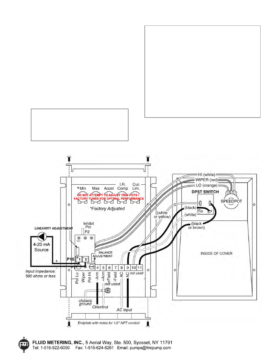
Wiring Diagram
Important Note:
Trimpots are factory tuned for
optimal performance. Adjustments in the field
should only be made with the guidance of FMI
support personnel or performed by an authorized
FMI factory representative. Before performing
any trimpot adjustments, contact FMI factory.
WIRING PROCEDURE
1) Remove the four (4) cover screws to remove the
cover and gain access to the terminal strip.
Note: When removing the cover, take care not to
damage the cover gasket or the wires connecting
the cover controls with the main circuit board.
2) If an external 4-20 mA control source is used,
(typically a sensor, analyzer, or PLC etc.),
connect the 4-20 mA output of this device to the
+1 and -2 terminals as shown below.
3) After all wiring is complete, replace the cover.
Take care to align the gasket and torque down
the four (4) cover screws such that the gasket is
evenly compressed and seals properly.
IN-CL-14
3/11/14 HW
Page 7 of 10