FMI CL1 User Manual
Page 2
Supply Voltage: 0-90 VDC (Supplied by C100A Controller)
CL Supply: 1/4” NPT female
CL Recirculation return: 1/4” NPT female
CL High Pressure outlet: 1/4” NPT female
Output Volume: CL1: 6.5 GPH max.
CL2: 15 GPH max.
Output Pressure: 125 psi max.
Environment: Humidity: 100% RH non-condensing
Temp: non-freezing to 104°F
Enclosure: Fiberglass
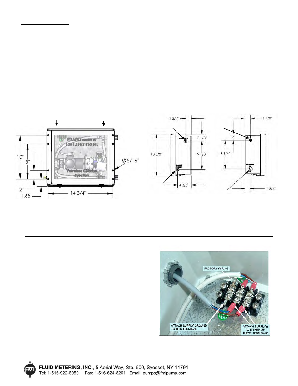
Dimensions: 15 1/2” x 13 3/8” x 6 3/4”
Weight: 18.6 lbs. (8.4 kg.)
CL SPECIFICATIONS
CL INSTALLATION & SETUP
The Chloritrol
®
CL prefers to “lift fluid” and therefore
should be located a minimum of 12 inches above supply
vessel. It should also be mounted in an accessible
location where the cover can be opened freely.
Diagram 5
illustrates the recommended mounting location, as well as
a typical system configuration.
MOUNTING
Securely fasten the CL to a wall location with its right side
convenient to the hypochlorite supply vessel. There are 4
mounting holes (5/16” dia) on each side of the CL
enclosure. Utilize at least 2 holes on each side for most
secure mounting.
Diagram 1 (left) shows the mounting
hole locations.
Diagram 2
(Right Side)
Diagram 3
(Left Side)
ELECTRICAL
On the upper left side of the Chloritrol® CL
enclosure is a 7/8” conduit opening for the electrical
supply (0-90 VDC source from the C100A or FMI
approved customer supplied voltage controller).
Note: See page 5 “Wiring Procedure” for
additional information regarding wire sizing.
1.
With the power off, and the manual speed dial
turned fully counterclockwise to the “0” position,
connect the C100A to the 120 VAC power
source.
2.
Connect the C100A Variable Speed DC Controller
to the Chloritrol
®
using 3 conductor cable.
3.
If electronic speed control is being used, connect
the 4-20 mA source (typically a sensor or
analyzer), to the 4-20 mA input of the C100A.
Diagram 4
Terminal Wiring
IMPORTANT NOTE: There are two (2) vent holes located at the top front of the enclosure (under the upper lip of the
enclosure cover). Do not close, seal, or obstruct these vent openings. They are designed to prevent hazardous gases from
building up in the enclosure over time.
See Diagram 1.
Vent
Vent
CL SUPPLY INPUT
ELECTRICAL
CL RETURN
TO SUPPLY
CL DISPENSE
IN-CL-14
3/11/14 HW
Page 2 of 10
Diagram 1
Mounting Holes